Last updated on May 24th, 2026 at 07:50 am
The hydraulic power pack emerged as an evolution of hydraulic technology rooted in principles established by early scientists and inventors, with the hydraulic press invented by Joseph Bramah in 1795 marking a pivotal moment for the field. Industry widely uses hydraulic power packs today for their efficiency, control, and ability to deliver high force in compact, reliable units.
Introduction to Hydraulic Power Packs
What is a Hydraulic Power Pack?
A hydraulic power pack, also known as a hydraulic power unit (HPU), is a self-contained system that generates, controls, and transmits hydraulic energy to power various forms of machinery. It serves as the heart of a hydraulic system, converting mechanical or electrical energy into fluid power. A typical power pack consists of a reservoir to hold hydraulic fluid, a pump to create flow, an electric motor or engine to drive the pump, and a series of valves to control the fluid’s direction, pressure, and flow rate.
These units are designed to apply significant force and provide precise control for a wide range of applications, from heavy industrial machinery to mobile construction equipment. The inherent ability of hydraulic systems to generate high power in a compact footprint makes them indispensable in modern engineering.
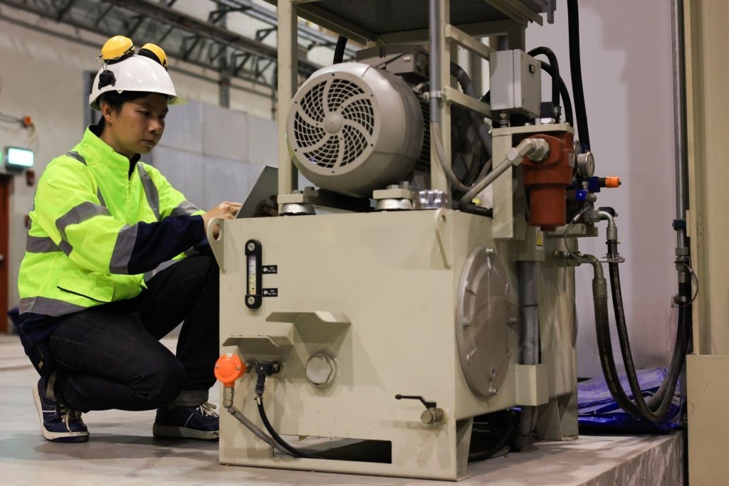
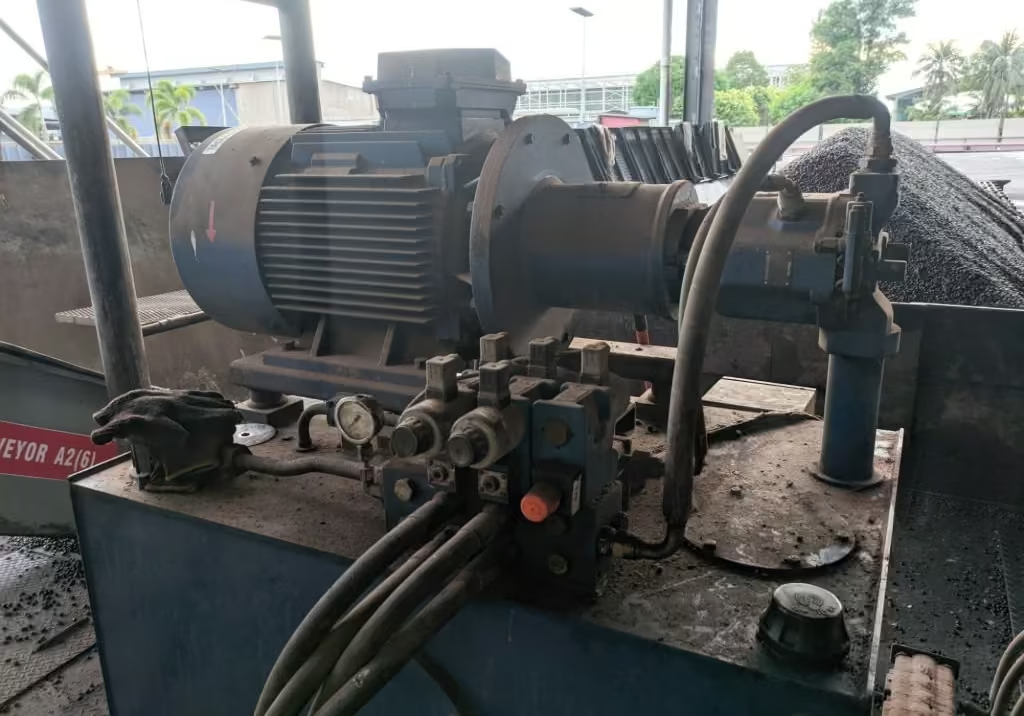
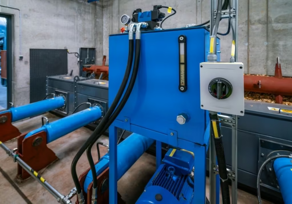
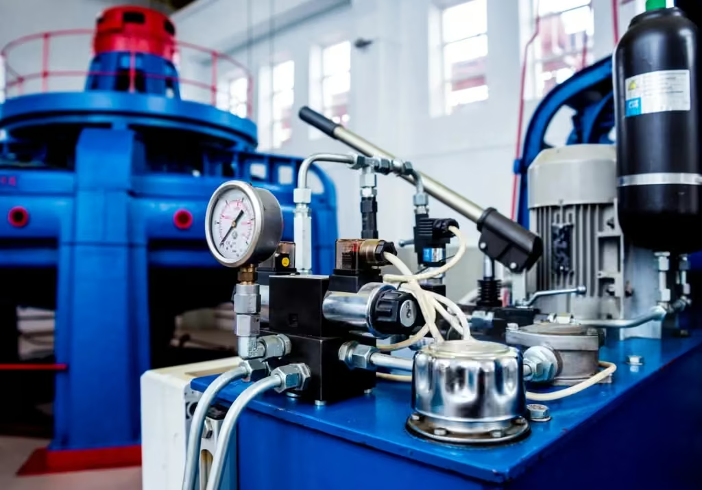
Hydraulic Power Pack in Factory
Fundamental Working Principle
The operation of a hydraulic power pack is governed by Pascal’s Law, a fundamental principle in fluid mechanics. This law states that pressure applied to an enclosed, incompressible fluid is transmitted undiminished to every portion of the fluid and the walls of the containing vessel. By pressurizing hydraulic fluid, a power pack can generate immense force, which is then used to perform work through actuators like cylinders and motors. The basic operational cycle of a hydraulic power pack is as follows:
- The prime mover (an electric motor or internal combustion engine) drives the hydraulic pump.
- The pump draws hydraulic fluid from the reservoir and forces it into the hydraulic circuit, converting mechanical energy into hydraulic (fluid) energy.
- The pressurized fluid is directed by control valves to an actuator (e.g., a hydraulic cylinder or motor).
- The actuator converts the fluid energy back into mechanical energy, performing work such as lifting a load or rotating a shaft.
- The fluid, having done its work, returns to the reservoir, where it is filtered and cooled before being recirculated.
Core Components and Their Functions
A hydraulic power pack is an assembly of various components, each playing a critical role in the system’s overall performance and reliability. These can be categorized into primary and auxiliary components.
Primary Components
1. Electric Motor/Engine
Function: Drives the hydraulic pump, converting electrical or chemical energy into mechanical power.
Characteristics: Power rating in kW or HP, usually with IP54 protection levels; selected based on required pressure and flow. Stall torque is a critical parameter. It is a torque required to stop the motor’s rotation. Excessive stall torque can overheat the motor, Damage motor windings and/or Burn driver circuits
2. Hydraulic Pump
Function: Converts mechanical power from the motor into hydraulic power by creating a flow of fluid.
Characteristics: Types include gear, vane, and piston pumps, each with specific pressure and flow capabilities.
3. Reservoir (Tank)
Function: Stores the hydraulic fluid, facilitates heat dissipation, and allows contaminants to settle.
Characteristics: Sized 3-5 times the pump’s flow rate per minute to ensure adequate cooling and fluid supply.
4. Valves
Function: Control the direction, pressure, and flow rate of the hydraulic fluid.
Characteristics: Includes directional control, pressure relief, and flow control valves, often integrated into a manifold block.
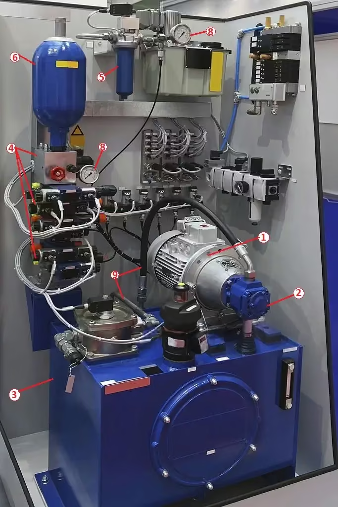
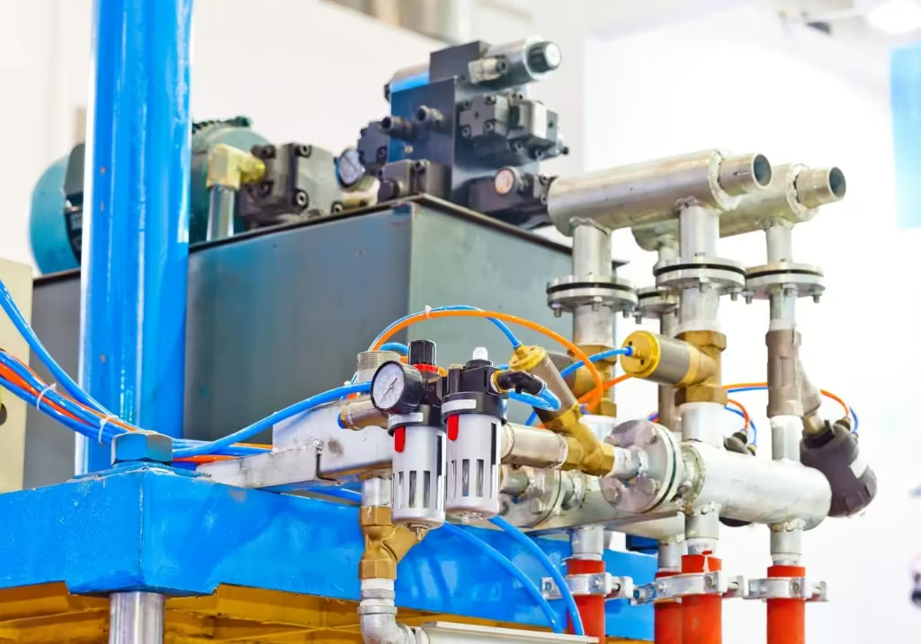
Hydraulic Power Unit Components
Auxiliary Components
5. Filters: Remove contaminants from the hydraulic fluid to protect system components. They are placed on the suction, pressure, or return lines.
6. Accumulators: Store hydraulic energy under pressure, absorb shocks, and maintain system pressure.
7. Coolers (Heat Exchangers): Regulate the temperature of the hydraulic fluid to prevent overheating and degradation.
8. Pressure Gauges: Monitor system pressure, aiding in diagnostics and ensuring safe operation.
9. Hoses and Fittings: Connect the various components, allowing fluid to flow throughout the circuit.
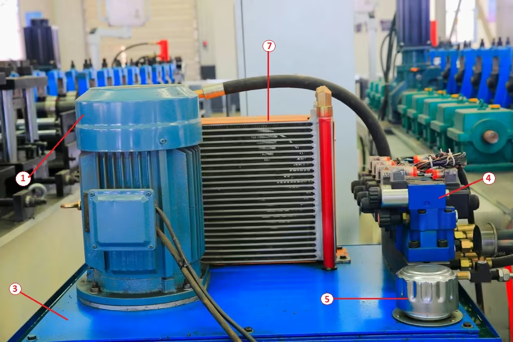
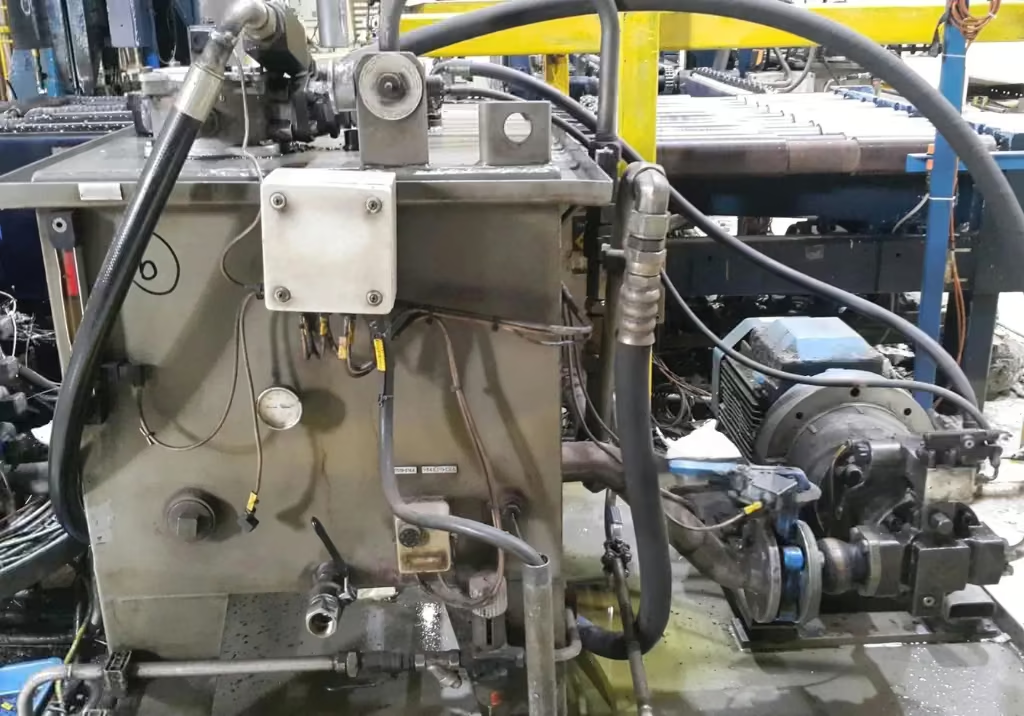
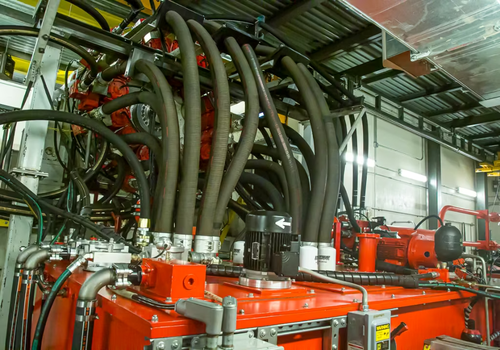
Hydraulic Power Unit with Oil Cooler
Hydraulic Power Pack Types
Hydraulic power packs convert mechanical power into hydraulic energy to operate various tools and equipment. These units come in numerous configurations based on power source, size, application, and pressure capacity.
Classification by Type of Power
Electric-Powered Hydraulic Power Packs
Electric power packs are among the most common types, available in DC and AC voltage configurations.
DC Electric Power Packs (12V/24V/48V)
Low-voltage DC units are ideal for mobile applications, vehicle-mounted systems, and portable operations. These compact units typically feature a cylindrical motor housing connected to a fluid reservoir and often include remote control functionality for convenient operation. They’re commonly used in dump trucks, trailers, tail lifts, and mobile equipment where battery power is readily available.
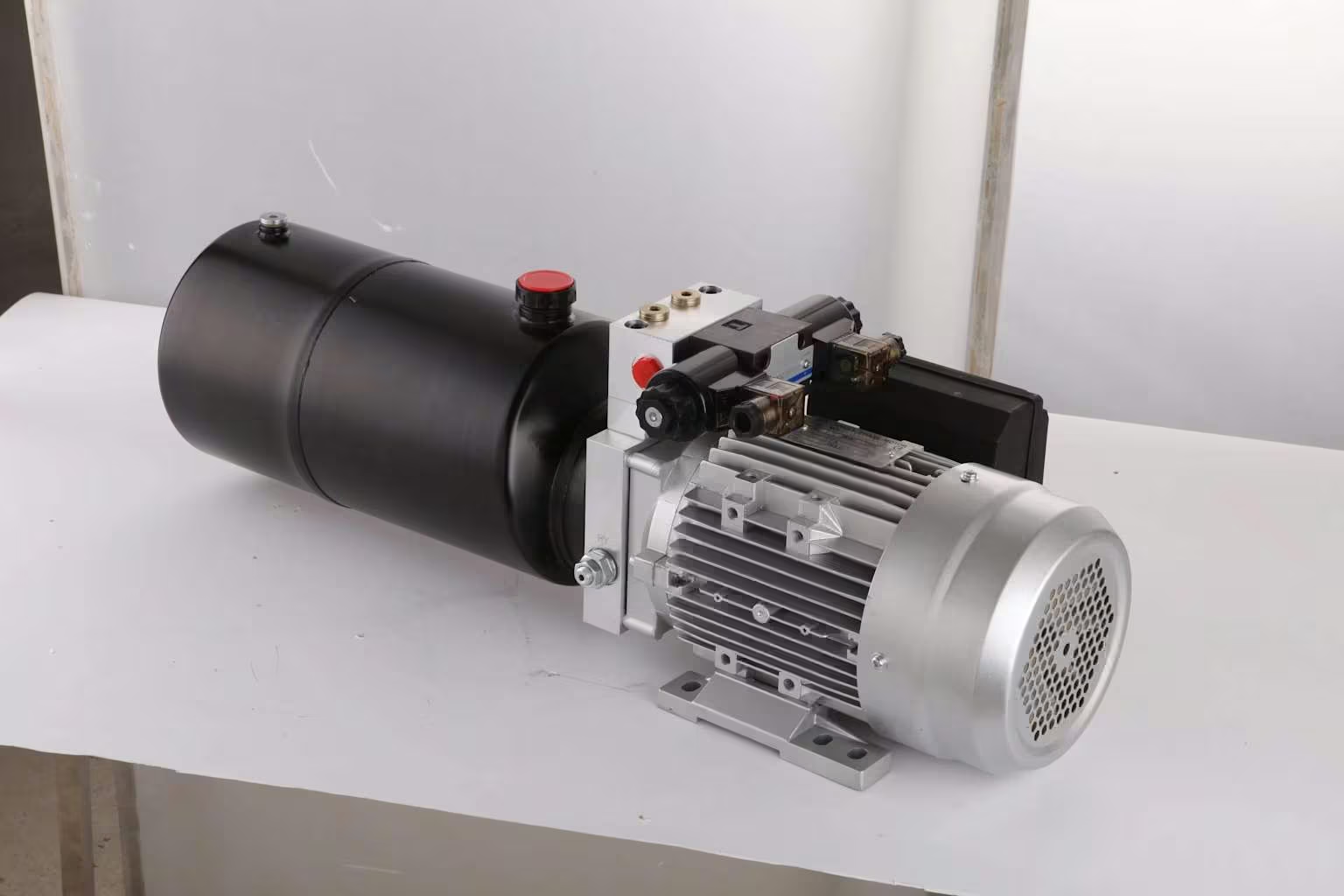
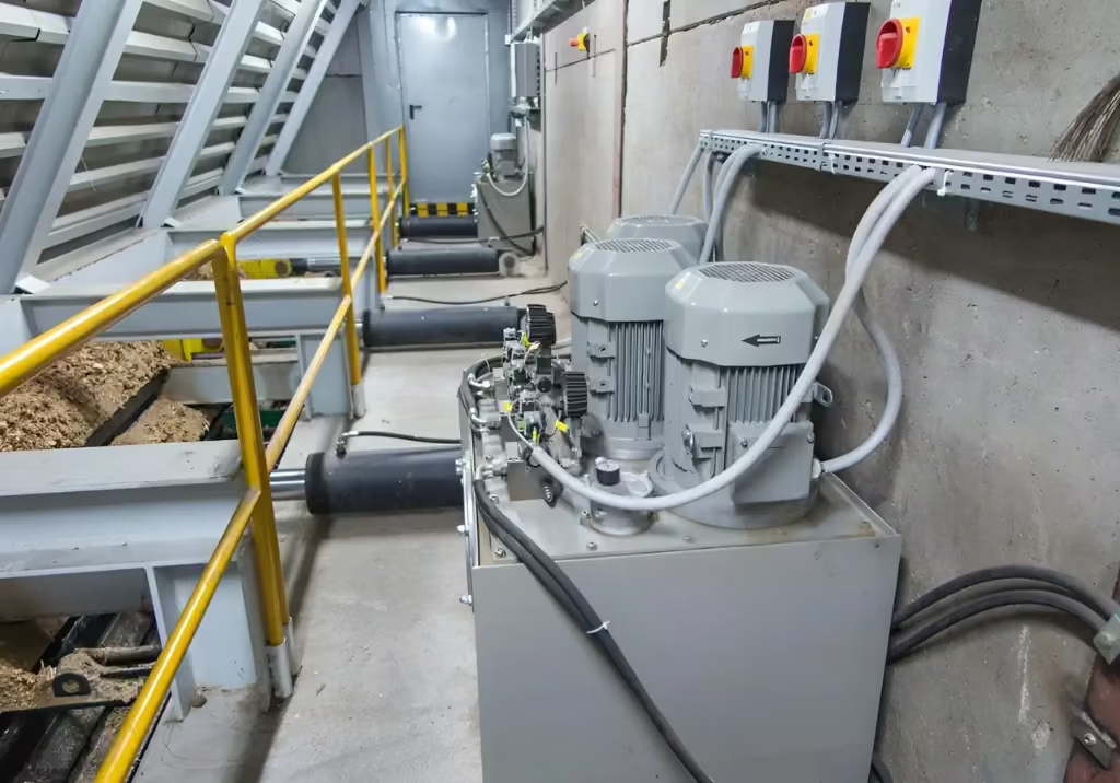
AC Electric Power Packs (110V/120V/220V/240V)
AC-powered units are designed for stationary industrial applications with reliable mains power. These systems range from compact units to large industrial power packs and typically feature electric motors mounted on hydraulic reservoirs with integrated pumps, valves, and cooling systems. They’re classified by pressure capacity ranging from low pressure (≤2.5 MPa) to ultra-high pressure (>32 MPa).
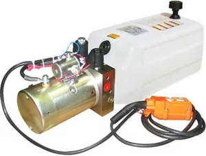
Electric (DC) Powered Hydraulic Power Pack
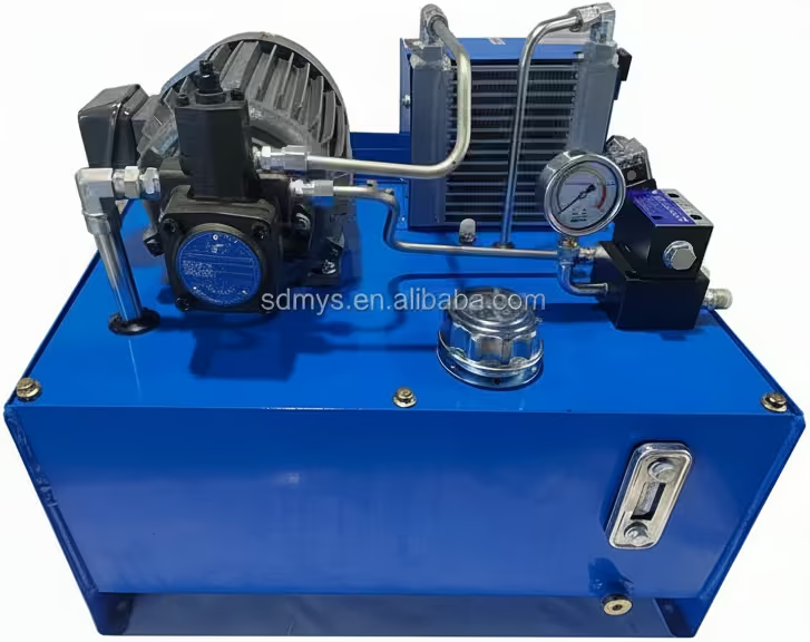
Electric (AC) Powered Hydraulic Power Pack
Combustion Engine-Powered Power Packs
Petrol/Gasoline-Powered Units
Petrol-powered hydraulic power packs offer excellent portability for field applications where electric power is unavailable. These units typically feature small gasoline engines (often Honda or Briggs & Stratton) coupled with hydraulic pumps and reservoirs, mounted on portable frames with wheels. They’re widely used in construction, demolition, and rescue operations.
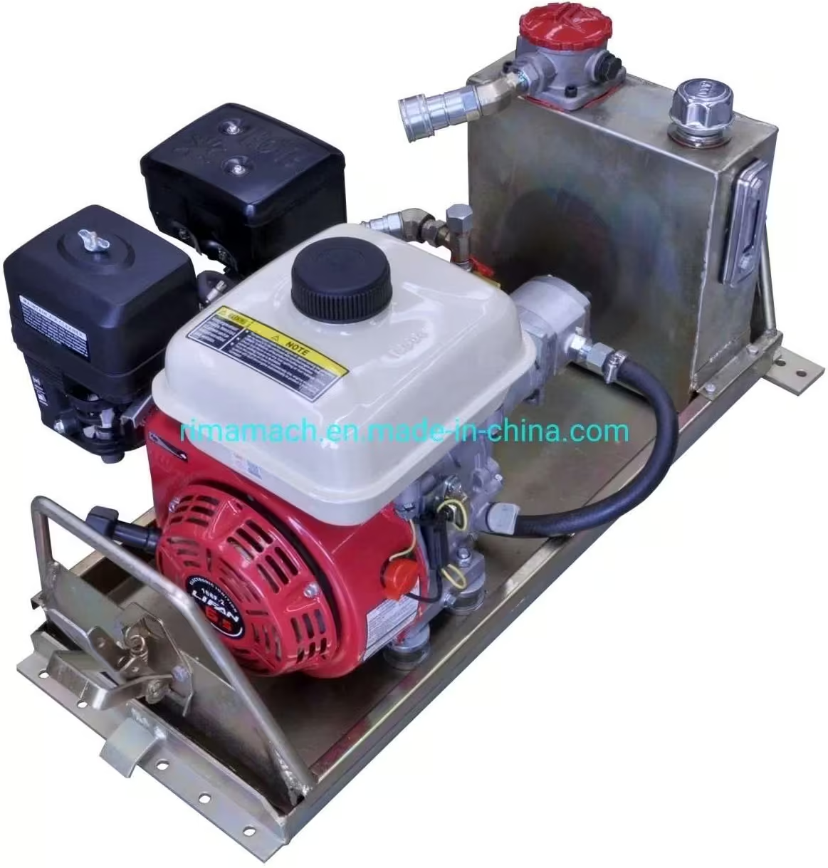
Petrol Powered Hydraulic Power Pack
Diesel-Powered Units
Diesel power packs provide robust, fuel-efficient operation for heavy-duty applications. These units feature diesel engines mounted on wheeled frames with hydraulic tanks, control panels, and gauges. Diesel units are preferred for extended operation periods, remote locations, and applications requiring high power output with lower fuel costs compared to petrol engines.
Gas-Powered Units
Gas-powered (propane/natural gas) hydraulic power packs offer clean-burning operation suitable for indoor or environmentally sensitive applications. These units combine gas engines with hydraulic systems on compact, portable frames.
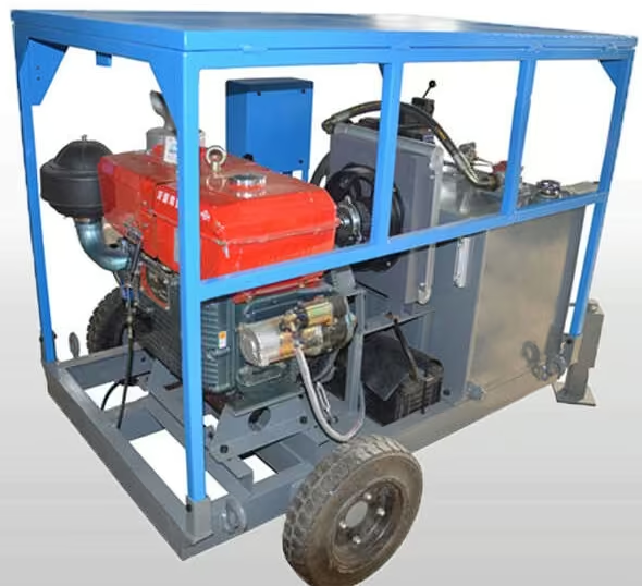
Diesel Powered Hydraulic Power Pack
Gas Powered Hydraulic Power Pack
Classification by Size
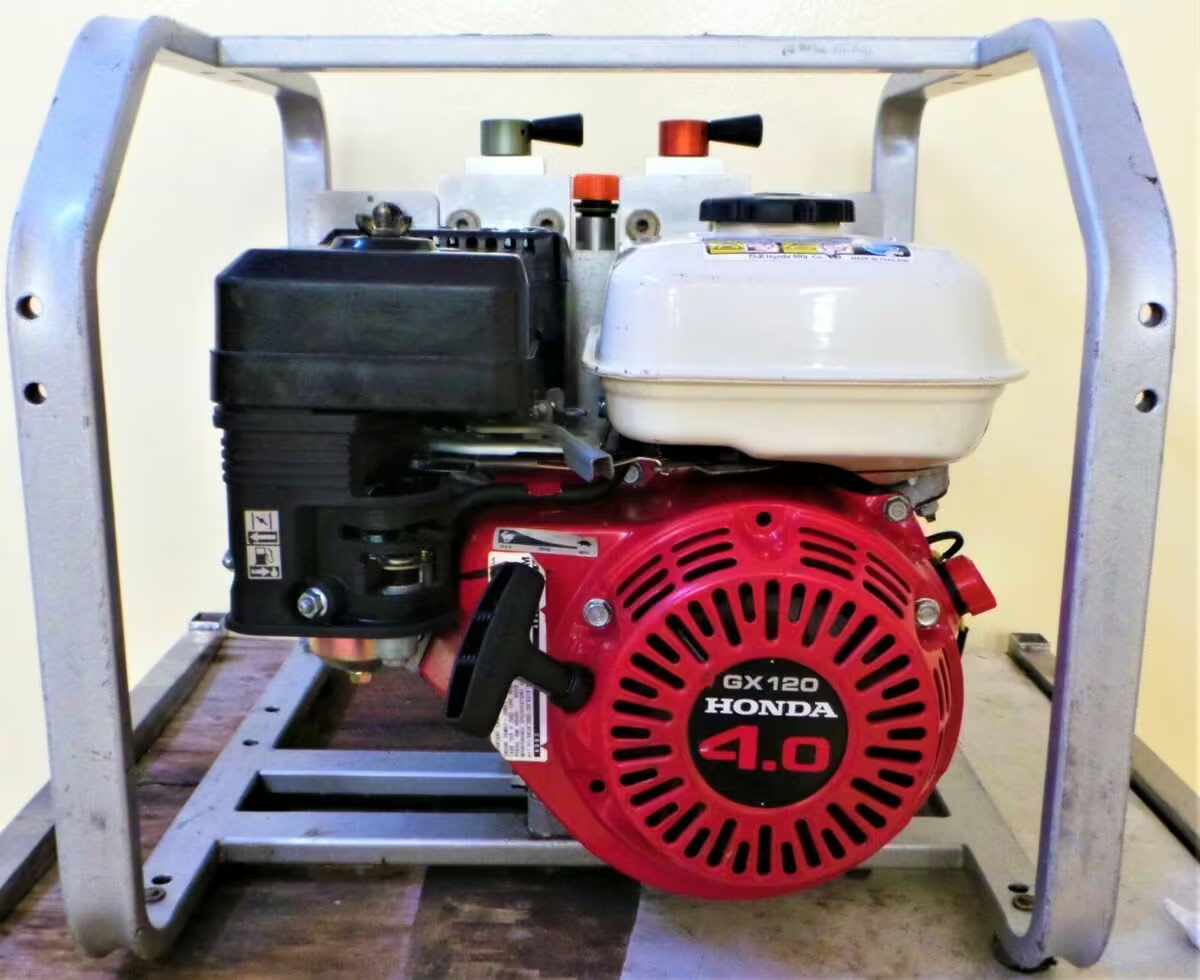
Mini/Micro Power Packs
Compact hydraulic power units are designed for space-constrained applications. These units feature integrated designs with small electric motors and reservoirs, typically offering flow rates of 0-20 lpm. Mini power packs are ideal for vehicle lifts, small machinery, and portable tools where space is limited but hydraulic power is essential.
Portable/Compact Power Packs
Medium-sized portable units balance power output with mobility, featuring protective frames, wheels, and carrying handles. These units are commonly used for handheld hydraulic tools, breakers, and cutters.
Mini/Compact Hydraulic Power Pack
Large-scale hydraulic power units serve centralized hydraulic systems in manufacturing facilities and heavy industry. These stationary units feature high-capacity reservoirs, multiple pumps, extensive valve manifolds, cooling systems, and control panels. They can supply hydraulic power to multiple machines simultaneously and are designed for continuous-duty operation.
Classification by Application
Hydraulic power packs can also be categorized by output flow characteristics (fixed displacement vs. variable displacement), degree of versatility (specialized vs. general-purpose), and mounting configuration (skid-mounted, frame-mounted, or integrated units).
The selection of hydraulic power pack type depends on factors including power requirements, mobility needs, available power sources, environmental conditions, duty cycle, and specific application demands. Electric units dominate stationary industrial applications, while combustion engine-powered units excel in mobile and remote operations. Subsea units serve the specialized needs of offshore industries, demonstrating the remarkable adaptability of hydraulic power technology across diverse environments and applications.
Sizing and Selection Methodology
Properly sizing a hydraulic power pack is crucial for ensuring optimal performance, efficiency, and longevity. An undersized unit will fail to meet performance requirements, while an oversized unit will be inefficient and costly. The sizing process involves a series of calculations to determine the required pressure, flow rate, and motor power.
System Sizing Calculations
The fundamental calculations for sizing a hydraulic power pack are as follows:
1. Pressure Requirement: The system pressure is determined by the force required by the actuator and its effective area.
2. Flow Rate Requirement: The flow rate determines the speed of the actuator. It is calculated based on the actuator’s volume and the desired cycle time.
3. Motor Power Calculation: The power required to drive the pump is a function of the system pressure and flow rate.
Component Sizing and Selection
Once the primary system parameters are established, individual components can be sized and selected.
- Pump Selection: The pump is chosen based on the required flow rate and maximum operating pressure. The main types are gear, vane, and piston pumps, each suited for different pressure and flow ranges.
- Reservoir Sizing: The reservoir should be large enough to dissipate heat and provide adequate fluid supply. A common rule of thumb is to size the reservoir at 3 to 5 times the pump’s flow rate in liters per minute.
- Valve Selection: Valves must be rated for the system’s maximum pressure and flow. Their port sizes are chosen to minimize pressure drop.
- Cylinder Sizing: The cylinder’s bore size is determined by the force requirement, and its stroke length is dictated by the application’s travel distance.
Design Calculations and Examples
This section provides a detailed, step-by-step guide to the design calculations required for sizing a hydraulic power pack, complete with practical examples derived from industry documents and tutorials.
The design of a hydraulic power pack follows a logical sequence of calculations to ensure all components are correctly sized for the application.
- Define Application Requirements: Start by clearly defining the work to be done. This includes the force required, the distance the load needs to move (stroke), and the time in which the operation must be completed (cycle time).
- Calculate Cylinder Parameters: Based on the force and stroke requirements, determine the appropriate hydraulic cylinder bore size and stroke length.
- Calculate Required Flow Rate: Determine the volume of oil the cylinder requires and calculate the necessary pump flow rate (in Liters Per Minute or Gallons Per Minute) to achieve the desired cycle time.
- Calculate Motor Power: Based on the system’s flow rate and operating pressure, calculate the required power for the electric motor (in Horsepower or Kilowatts).
- Size the Reservoir (Tank): Determine the appropriate size for the hydraulic reservoir to ensure adequate cooling and fluid supply.
- Calculate Pressure Losses: Analyze the system for potential pressure losses in hoses and fittings to ensure the pump can deliver the required pressure at the actuator.
Working Example
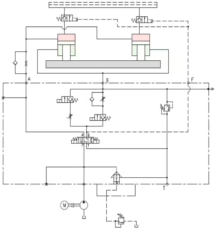
Hydrulic Schematic for a Power Pack (Power Unit)
Once the calculations are complete and every component of the hydraulic power pack is carefully selected for the specific application, the next step is to bring everything to life through a well-structured hydraulic schematic. This schematic becomes the “blueprint” of the entire system – the visual story of how hydraulic energy is created, controlled, and delivered to perform real work. A clear schematic ensures that every component communicates perfectly, preventing failures and making future troubleshooting far easier. By making such schematics, end user can understand not just what the components are, but why they are placed in a certain sequence and how they work together to deliver smooth and consistent hydraulic power.
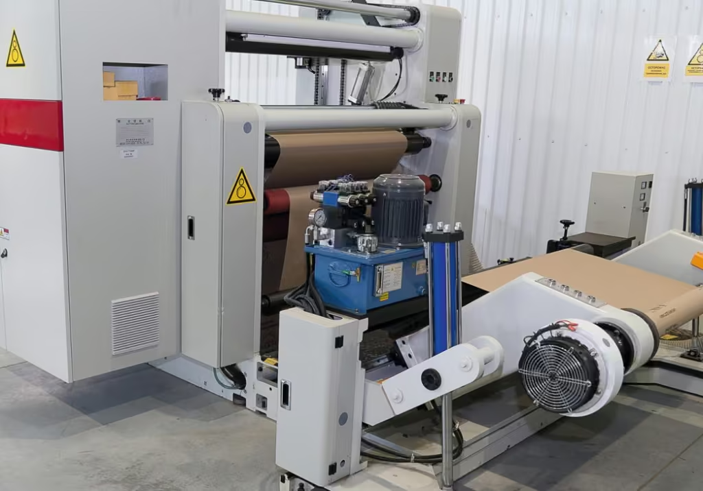
Here is a pictorial layout from a real industrial environment – an Automatic Coil Coating Line used in Aluminum and Steel Plants. This system relies on a dedicated hydraulic power pack to operate various stages of the coating process.
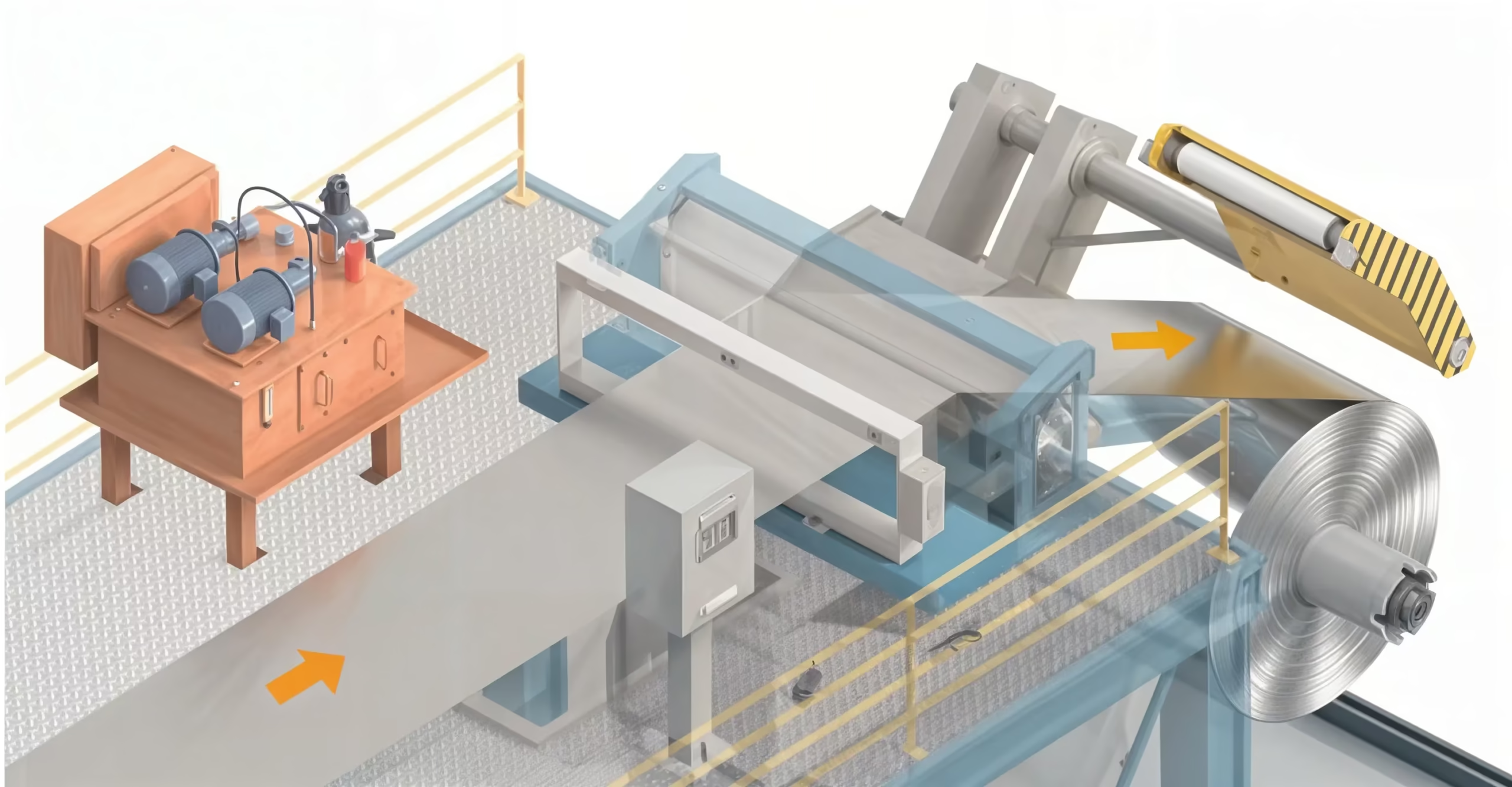
Pictorial Layout of Automatic Coil Coating Plant for Aluminum and Steel which uses a Hydraulic Power Pack for it’s operation
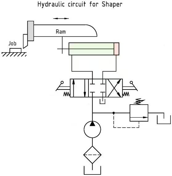
Hydraulic Schematic of Shaper Machine (Source: R. Ramakutty)
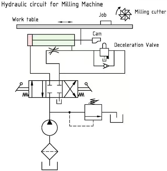
Hydraulic Schematic of Milling Cutter Machine (Source: R. Ramakutty)
Hydraulic Schematic of Press Machine (Source: compraco.com)
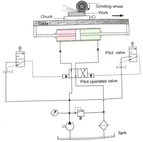
Hydraulic Schematic of Shaping & Grinding Machine (Source: enggarena.net)
eConfiguration for Hydraulic Power Units
Many manufacturers offer configuration tools to simplify the selection process for end users.
Bucher provides a dedicated design configurator for their GPP power packs, allowing users to tailor the system to their specific requirements.
To use this configurator effectively, you can refer to Bucher’s official guide for configuring GPP power packs.
HAWE Hydraulic offers a comprehensive selection configurator for power packs across various industries – such as machining, plastics, presses, metallurgy and many others.
HAWE even offers virtual tour independently to familiarize with compact power units. At your time, without travel expenses and interactively at the location of your choice. – I highly recommended checking out this virtual tour.
Bosch Rexroth offers a quotation configurator to help users generate power pack quotes.
To use this tool correctly, refer to Rexroth’s official guide for configuring and generating quotations.
Hydac Australia also offers design a hydraulic power unit quickly and efficiently, customised to your specific requirements.
Applications Across Industries
Hydraulic power packs are utilized in a vast array of industries due to their high power density and precise control. Their applications range from large-scale industrial processes to compact mobile equipment.
- Manufacturing and Machining: Powering hydraulic presses, machine tools, injection molding machines, and automated clamping systems on CNC machines.
- Construction: Driving heavy equipment such as excavators, cranes, bulldozers, and concrete pumps.
- Automotive: Used in vehicle braking systems, power steering, and lifting equipment in service garages.
- Aerospace: Operating landing gear, flight control surfaces, and cargo doors.
- Marine: Powering steering systems, winches, cranes, and ballast pumps on ships and offshore rigs.
- Mining: Driving drilling rigs, crushers, and material handling equipment in harsh environments.
- Energy Sector: Used in wind turbine pitch control, solar panel tracking systems, and oil and gas exploration equipment.
Below are few application where Hydraulic Power Unit is being used.
Hydraulic solutions for trash-rack cleaners in hydroelectric power plants
Hydraulic Power Pack in Paper Bag Production Plant (Source: ukobf.ru)
Hydraulic Power Pack in Bay Platform to Loading Platform using Hydraulic Motor
Hydraulic Power Pack in Biofuel Boiler House
Hydraulic Power Pack in Chain & Roller Plant
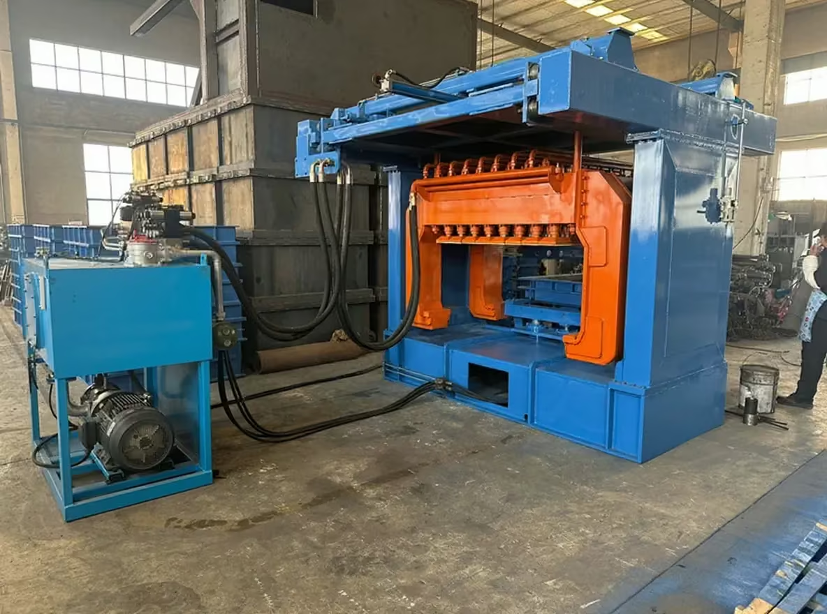
Hydraulic Multi Piston Sand Molding Machine using Powerpack (Source: besttechmachinery.com)
Foundry Efficiency Hydraulic Multi Piston Green Sand Molding Machine Working Process
— foundry machine & shot blasting machine (@CassieHan9) November 21, 2025
Whatsapp+8618765972210#greensandmoldingmachine #sandmoldingmachine #hydraulicsandmoldingmachine #foundrysandmoldingmachine #foundrysolutions #foundryplant #fundición pic.twitter.com/J0KDeTGVFx
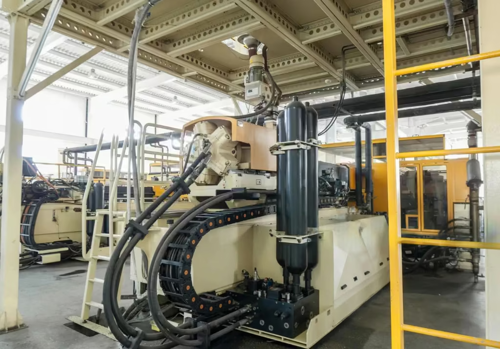
Hydraulic Power Pack in Production Plant for Plastic Part
Hydraulic Power Pack in HydroElectric Power Plant
Hydraulic Power Pack in Biomass Scraping Feeder
Hydraulic Power Pack in Foundry Industry
Hydro also provides range of other applications of hydraulic power pack.

A Roller Coaster in an Amusement Park

A Closeup view of a Roller Coaster Slide in an Amusement Park
A Roller Coaster Slide in an Amusement Park using a Hydraulic Powerpack
A Big Hydraulic Powerpack used for roller coaster in an amusement park ride (Source: x.com/supkophoto)
Cost Analysis and Considerations
The cost of a hydraulic power pack can vary significantly based on its size, complexity, and features. Understanding the factors that influence price is essential for making a costeffective purchasing decision.
Factors Influencing Cost
- Size and Capacity: Larger units with higher pressure and flow ratings are inherently more expensive.
- Component Quality: The brand and quality of components (pump, motor, valves) have a major impact on price and reliability.
- Customization: Standard, off-the-shelf units are more affordable, while custom engineered solutions for specific applications command a higher price.
- Materials and Construction: The use of specialized materials, such as stainless steel for corrosive environments, increases cost.
- Features: Additional features like advanced cooling systems, sophisticated filtration, and electronic controls add to the overall price.
Approximate Price Ranges
While prices vary widely, the following provides a general idea of the cost for different types of hydraulic power packs:
- Small, Portable Units (1-5 HP): $2,000 – $7,000
- Standard Industrial Units (10-25 HP): $8,000 – $20,000
- Large, Custom-Engineered Units (50+ HP): $25,000 – $100,000+
Total Cost of Ownership
When evaluating the cost of a hydraulic power pack, it is important to consider the total cost of ownership (TCO), not just the initial purchase price. TCO includes:
- Initial Purchase and Installation Costs
- Operating Costs: Energy consumption, hydraulic fluid, and filter replacements.
- Maintenance and Repair Costs: Scheduled maintenance and unexpected repairs.
- Downtime Costs: Production losses incurred during system downtime.
Investing in a higher-quality, more efficient unit may result in a lower TCO over the system’s lifespan.
Maintenance & Troubleshooting
Proper maintenance determines whether your hydraulic power pack delivers years of reliable service or becomes a source of costly downtime. Since hydraulic systems circulate compressed fluids through pumps, valves, and actuators, contamination causes significant internal damage and accelerated wear making filtration the cornerstone of any maintenance program.
Benefits: Extends component lifespan by 2-3x, reduces energy consumption, minimizes downtime, and lowers total cost of ownership.
Maintenance: Best Practices for Longevity and Performance
1. Filtration Systems: Quality filters include bypass indicators (pressure gauges, transducers, pop-up indicators, or warning lights) that signal when replacement is needed. Filters are located at tank top, return lines, pressure lines, and within specialized components.
Hydraulic Power Unit: Pressure Inspection & Maintenance
Best Practices: Monitor bypass indicators regularly (trigger at two-thirds capacity), inspect breather caps weekly, upgrade to synthetic media filters, and maintain detailed part numbers. Replace all filters immediately after pump failures or contamination events.
2. Fluid Management
Daily: Check reservoir levels and investigate sudden drops. Monthly: Conduct rotating oil analysis testing for viscosity changes, contamination, additive depletion, and oxidation. Regular: Inspect breather caps weekly, ensure proper venting, and clean reservoirs during oil changes.
3. Component Inspection
Hoses (Weekly): Check for bulging, kinks, abrasion, fitting leaks, and proper routing away from heat. Accumulators (Monthly): Verify pre-charge pressure, check for damage, test response time, and replace per manufacturer intervals (5-10 years). Pressure (Daily): Observe system pressure, filter indicators, and circuit pressures.
4. Leak Detection: Implement daily visual inspections, ultrasonic detection for hidden leaks, monthly comprehensive audits, and immediate repair of all leaks. Small leaks can cause catastrophic failures if units run dry.
5. Heat Management: Hydraulic fluid degrades rapidly above 150°F. Keep heat exchangers clean, conduct thermal imaging surveys, verify adequate airflow, monitor fluid temperature, investigate temperature increases immediately, and upgrade cooling capacity if needed.
Common Troubleshooting Scenarios
System Overheating
Possible Causes: Low fluid level, clogged cooler, incorrect fluid viscosity, high ambient temperature.
Corrective Actions: Top up fluid, clean or replace cooler, use correct fluid, improve ventilation.
Slow Operation
Possible Causes: Worn pump, internal leakage, low fluid level, clogged filter.
Corrective Actions: Repair or replace pump, identify and fix leaks, top up fluid, replace filter.
Excessive Noise
Possible Causes: Air in the system (aeration), pump cavitation, worn components.
Corrective Actions: Bleed air from the system, check suction lines for leaks, inspect and replace worn parts.
Safety Standards and Best Practices
Working with high-pressure hydraulic systems presents significant safety risks. Adherence to established safety standards is crucial.
- ISO 4413:2010: This is the primary international standard for the general rules and safety requirements for hydraulic fluid power systems and their components.
- Lockout/Tagout (LOTO): Always de-energize and lock out the power source before performing any maintenance or repair work.
- Personal Protective Equipment (PPE): Wear appropriate PPE, including safety glasses and gloves, when working on hydraulic systems.
- High-Pressure Injection Injuries: Never use your hands to check for leaks. High pressure hydraulic fluid can penetrate the skin, causing severe injury or death. Use a piece of cardboard or wood to locate leaks.
Future Trends and Advanced Technologies
The hydraulics industry is continuously evolving, with a focus on improving efficiency, intelligence, and environmental friendliness.
Energy Efficiency and Sustainability
There is a growing demand for more energy-efficient hydraulic systems. Key technologies driving this trend include:
- Variable Speed Drives (VSDs): VSDs match the motor and pump speed to the system’s demand, significantly reducing energy consumption compared to fixed-speed systems.
- Load-Sensing Systems: These systems adjust the pump’s output to match the load requirements, minimizing wasted energy.
- Energy Recovery Systems: In certain applications, energy from braking or lowering loads can be captured and reused, further improving efficiency.
Smart Hydraulics and Industry 4.0
The integration of electronics and software is transforming hydraulic systems, making them smarter, more connected, and easier to control.
- IoT Integration: The Internet of Things (IoT) allows for the remote monitoring of hydraulic systems. Sensors collect data on pressure, temperature, flow, and fluid condition, which can be analyzed to predict failures, optimize performance, and schedule maintenance proactively.
- Electro-Hydraulics: The combination of electronic control with hydraulic power offers the best of both worlds: the high force of hydraulics and the precision of electronics. This is leading to the development of highly sophisticated and responsive systems.
- Digital Control and Industry 4.0: Hydraulic power packs are becoming integral components of Industry 4.0 environments. With digital communication protocols like CAN-BUS and Ethernet, they can be seamlessly integrated into factory automation systems, enabling real-time data exchange and remote control.
Now that you have your power pack designed and every component selected, the next step is ensuring your system stays cool under load. Head over to the next post in this series:
👉 Hydraulic Oil Cooler Sizing: How to Select the Right Oil Cooler for Your Power Pack
It covers all four sizing methods — including a fully worked example for a 22 kW power pack — so you can confidently select the right cooler for your application.