Last updated on June 8th, 2025 at 02:31 pm
Ever wondered how hydraulic systems stay steady under different loads? Knowing the difference between pre compensation and post compensation makes it much clearer! Both types of compensation system help to maintain a stable flow as pressure varies.
But before we get into the details, Let’s first understand what ‘compensation’ really means!
Why do we need a Compensation System?
Fig. 1 shows the symbols for a flow control valve and a pressure-compensated flow control valve. Notice the highlighted arrow in the pressure-compensated symbol, which indicates the added pressure compensation feature.
Hydraulic systems work based on two fundamental factors: pressure and flow.
Here’s an important fact: A system operating at high pressure will have less flow, while a system with low pressure will have high flow.
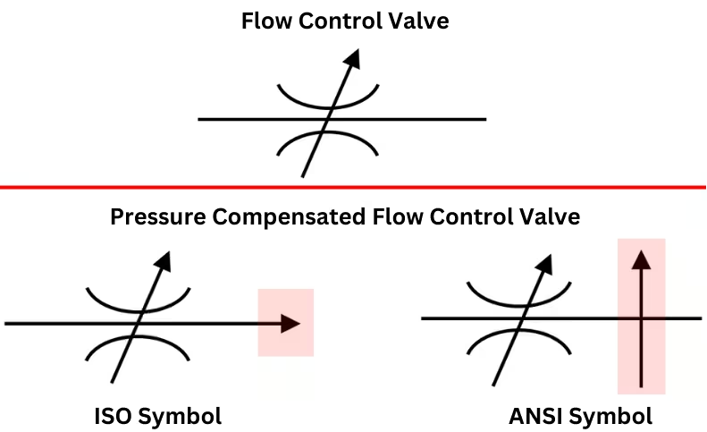
Fig.1: Symbol for Flow Control Valve vs Pressure Compensated Flow Control Valve

Fig.2: Conveyor in a Food Plant
Now, imagine this scenario: In the conveyor system shown in Fig. 2, let’s replace the food items with heavy motors. Based on the above principle, if there are only a few motors on the conveyor, it will move quickly. But if the conveyor is loaded with many motors, it will slow down.
This variation in conveyor speed can lead to increased work hours, which ultimately affects productivity and costs. Ideally, we want the conveyor to move at a consistent speed, no matter how many motors it is carrying.
To achieve this, we can use a flow control valve to regulate the flow to the conveyor. However, manually adjusting the flow control setting every time the load (number of motors) changes is neither practical nor efficient.
This is where a pressure-compensated flow control valve comes into play. This type of valve automatically maintains a constant flow, regardless of pressure variations caused by changes in the load (in this case, the number of heavy motors).
There are two types of these flow control valves:
- Pre-compensated
- Post-compensated
Each has its own role in maintaining a stable hydraulic system.
Pressure Drop & Flow Stability in Hydraulic Circuits
Let’s break it down with the help of three hydraulic circuits.
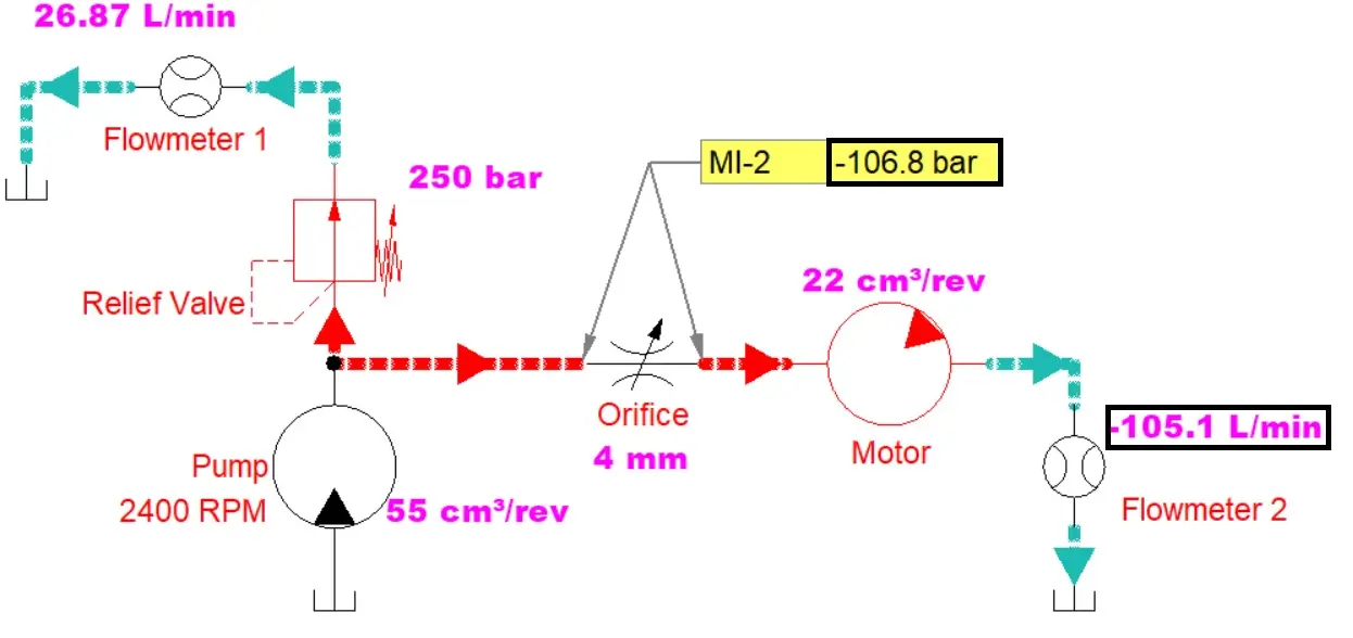
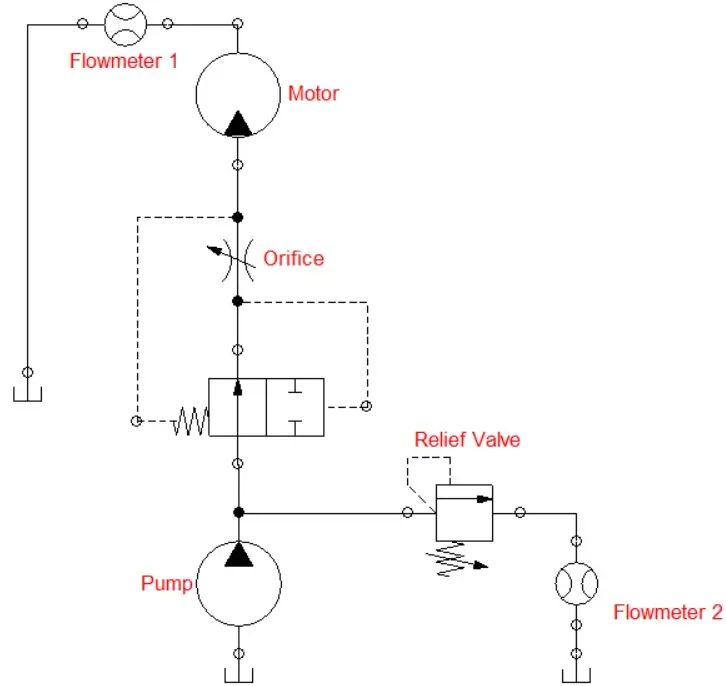
Pressure Drop across orifice with 250bar Relief Setting
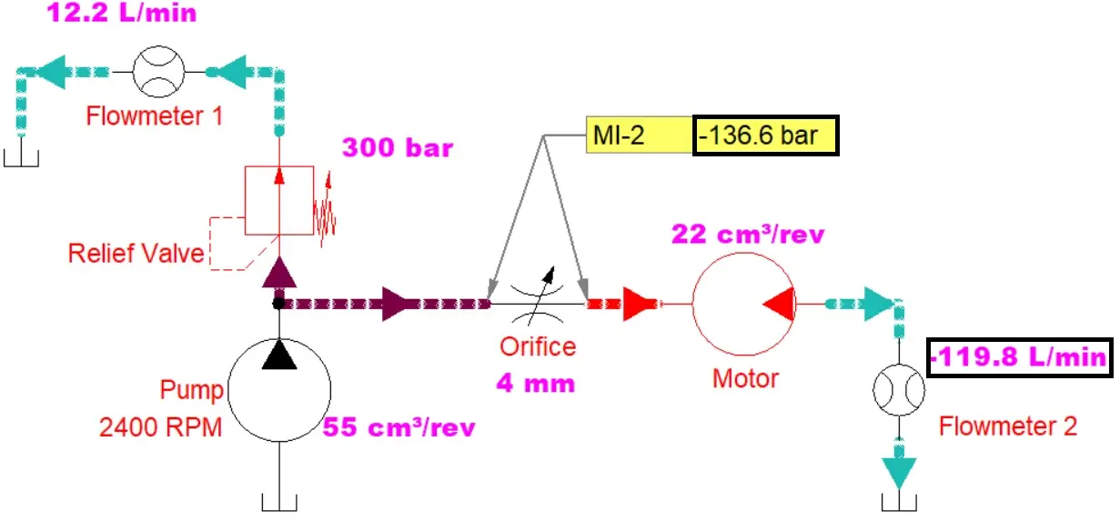
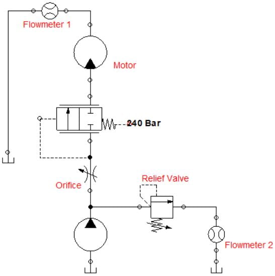
Pressure Drop across orifice with 300bar Relief Setting
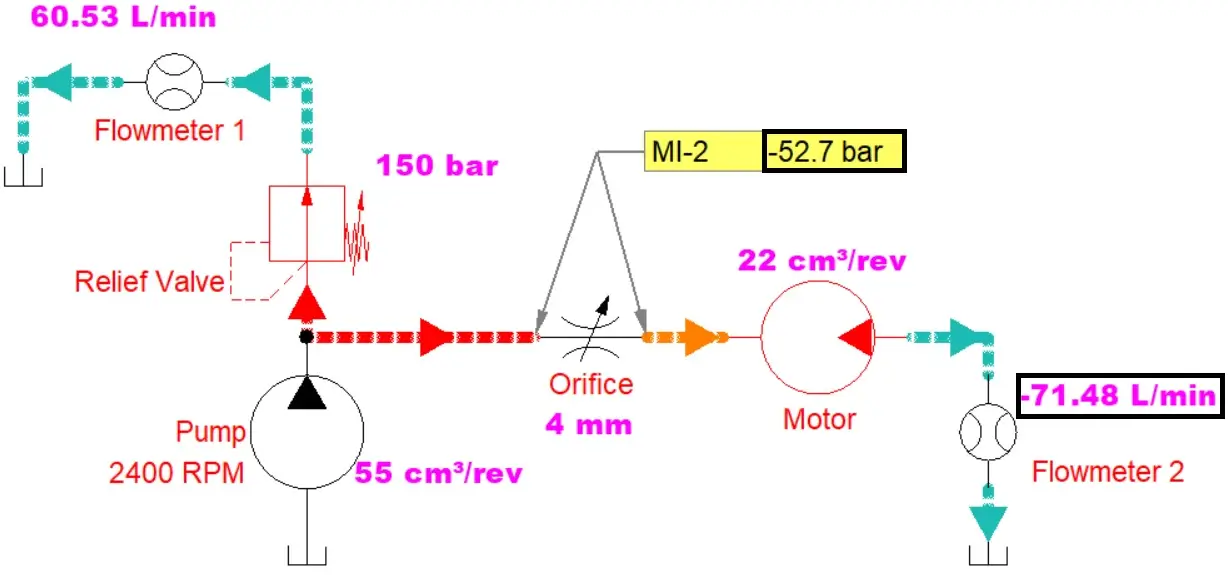
Pressure Drop across orifice with 150bar Relief Setting
In above examples, the pump and motor size, orifice size, and load on motor kept the same, but the relief valve setting has been varied.
As shown in condition 1 and 2, as we increase the relief valve setting from 250 to 300Bar, the pressure drop across the orifice goes up (ignore the negative sign) too. This happens because the pressure before the orifice (set by the relief valve) increases, while the pressure after the orifice (load on motor) stayed the same.
- With a higher relief valve setting, the flow is forced through the orifice since it can’t escape through the relief valve. And as a result, the flow to the motor increases, which you can see on flowmeter 2.
In the third circuit, when we lower the relief valve setting, the pressure drop across the orifice decreases. This happens because the pressure before the orifice (set by the relief valve) decreases, while the pressure after the orifice (load on motor) stayed the same.
- With a lower relief valve setting, more flow goes through the relief valve, so ultimately flow to the motor decreases, as shown on flowmeter 2.
This leads us to an important insight: oil flow is directly proportional to the pressure drop across the orifice.
(Note: Do not compare Pressure Drop with Pressure)
So, if we can maintain a constant pressure drop across the orifice, we’ll have steady oil flow, regardless of how much the load changes. This is the key to achieving stability in hydraulic systems, and it’s what compensation is all about.
Pre Compensation Hydraulic Circuit
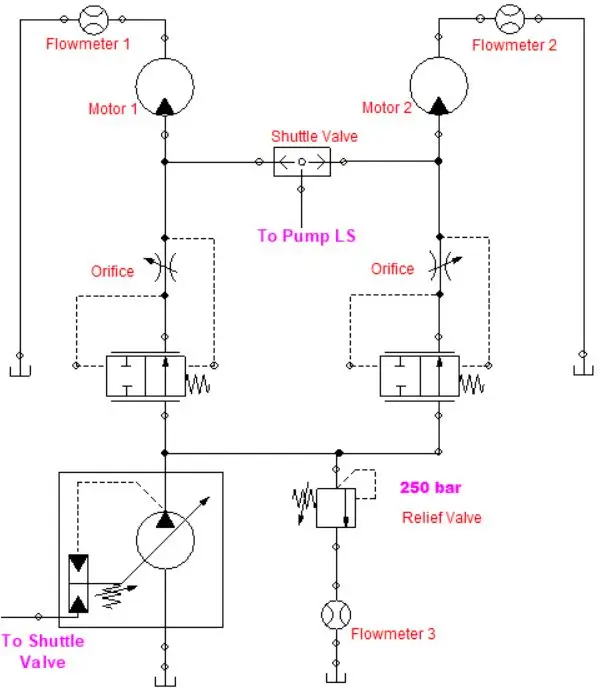
Pre-Compensation Hydraulic System with Two Motor
Post Compensation Hydraulic Circuit
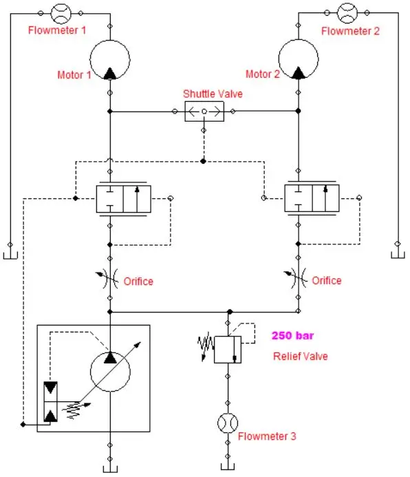
Post Compensation Hydraulic System with Two Motor
What would happen if we changed the compensator of the second motor to a normally open configuration?