Last updated on June 8th, 2025 at 02:31 pm
For many years, mobile equipment like tractors and loaders uses unique hydraulic steering systems (also called hydraulic power steering) to steer the machines. This unique system uses a steering control unit (SCU), which is rotated by the steering wheel and steering shaft.
Other than tractors and loaders, this unique system is also used in many other applications.
Application of Steering Unit
- Agricultural Equipment: Tractor, Front End Loader
- Construction Equipment: Backhoe Loader, Wheel Loader, Excavator (Wheeled), Dozer, Grader
- Lawn, Garden & Municipality: Golf Cart, Sweeper, Lawn Mower
- Transport Equipment: Truck, Forklift
- Marine: Deck Boat
- Autonomous Vehicle
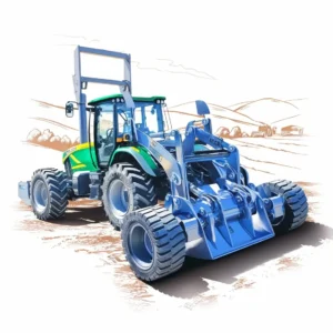
Agriculture Equipment
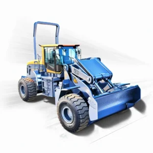
Construction Equipment
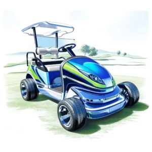
Lawn, Garden & Municipality
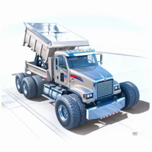
Transport Equipment
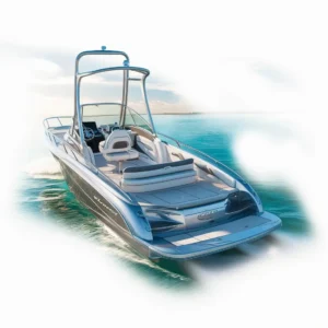
Marine

Autonomous Vehicle
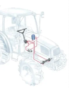
Hydraulic Steering System Layout in Tractor (Source: Ognibene)
Steering Unit Component
The SCU is responsible for completing two tasks related to steering a tractor. The SCU must control the direction of oil flow (right steer and left steer) and the quantity of oil flow (dictates how fast the wheels are turned).
Primary components of SCU includes:
- Gerotor assembly
- Drive shaft
- Control sleeve
- Centering pin
- Control spool
The internal components of an SCU are rotated by means of a Steering wheel and steering shaft.
- The steering wheel’s drive shaft is splined to the control spool.
- The control spool is coupled to the control sleeve through a centering pin and centering springs.
- The centering pin fits loosely inside the control spool and has a tight fit inside the control sleeve (because of pin diameter), letting the sleeve follow the spool when the wheel is turned.
- When the steering wheel stops, the centering springs bring the control spool/sleeve assembly back to the center position.
- As the control spool/sleeve assembly turns, the centering pin makes the drive shaft rotate.
- This drive shaft is connected to the internal gerotor, which spins within the gerotor assembly.
- The SCU housing, control spool, and control sleeve together function as a rotary directional control valve (DCV).
The stationary parts in the SCU include the gerotor’s ring gear, the housing, the spacer/wear plate, and the end plate/cover plate.
(Source: Danfoss)
Steering Unit Design
Alright!, So you know what are the Internal Components of SCU and how they work with respect to each other. But these components are basic and standard ones, and to make SCU work efficiently and more importantly protect, we must design it in a way that it serves the desire purpose. Let’s checkout how we can design with the help of schematic. Here I have added standard schematic of steering unit, with respect to standard configured SCU I have presented variety of internal steering valve options one by one which have their unique use. To make it more easier to identify, I have added Green Colour Text next to the valve option.
- Inlet Check Valve
- Inlet Relief Valve
- Check Valve for Emergency Steering
- Cylinder Port Relief Valve
- Anti Cavitation Check Valve
- Load Sensing Relief Valve
The last steering valve option – load sensing relief valve’s schematic is different from standard configuration. we will discuss working of load sense steering control unit in detail, but as we are discussing all valve options of steering unit, I have included ‘relief valve for Load Sense System’ here as well, so that all valve options are covered in a single place. and once again all six valve options including ‘relief valve for load sense system’ are optional and can be added to steering unit based on application.
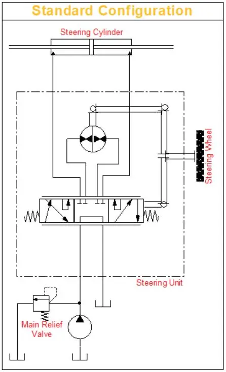
Steering Unit Standard Configuration
Inlet Check Valve
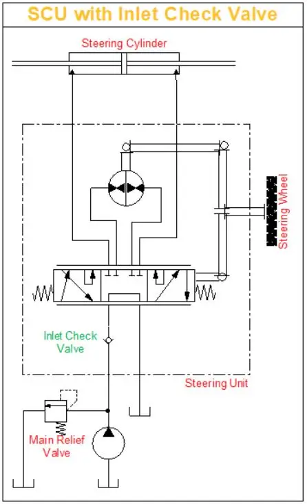
Steering Unit with Inlet Check Valve
Inlet Relief Valve
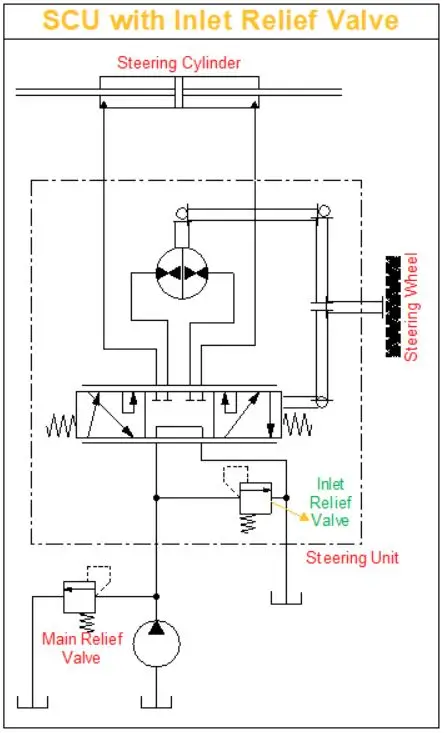
Steering Unit with Inlet Relief Valve
Manual Check Valve
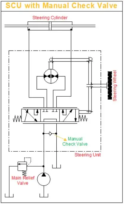
Steering Unit with Manual Check Valve
Port Relief Valve
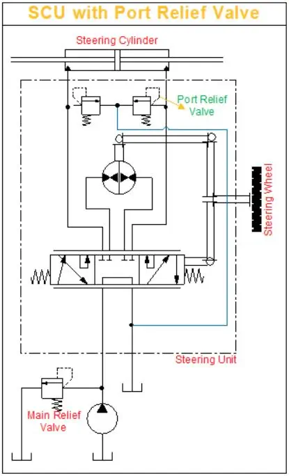
Steering Unit with Port Relief Valve
Anti Cavitation CV
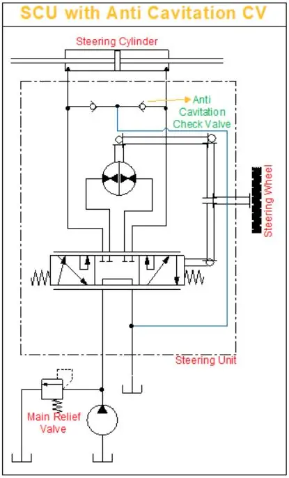
Steering Unit with Anti Cavitation Check Valve
Inlet Check Valve:
When external forces act on the steering cylinder, they can sometimes cause the steering pressure to rise higher than the main system pressure. This increase could force the steering oil to flow backward through the SCU, leading to what’s known as steering kickback—where the steering wheel moves abruptly in the opposite direction. To prevent this, the inlet check valve is used. It stops the oil from flowing back, ensuring the steering wheel remains stable and preventing any sudden, unwanted movements.
Inlet Relief Valve:
Most hydraulic steering systems include a dedicated relief valve specifically for the steering circuit, often located within the SCU. The pressure setting for the steering relief valve is usually set lower than the main system pressure. If the hydraulic pump is dedicated solely to steering, the main system relief valve may not be needed, as the inlet relief valve would be sufficient. However, in cases where a fixed-displacement pump’s flow is split by a proportional flow divider valve, having the main system relief valve becomes necessary to manage and protect the overall hydraulic system properly.
Manual Check Valve:
In a fully hydraulic steering system, the SCU has a feature called emergency or manual steering mode that helps you steer if the engine stalls or the hydraulic pump stops working. The manual check valve is located at the SCU’s inlet and connects the inlet port to the tank return port.
If the pump isn’t supplying oil, this valve allows the SCU’s gerotor to pull oil directly from the reservoir. This ensures the steering system still has oil for emergency use. As the gerotor spins, it pulls oil through the valve, then directs it through the control assembly and into the steering cylinder, allowing you to steer manually even when the engine or pump fails.
Port Relief Valve:
Whenever a directional control valve (DCV) is in the neutral position, the part of the circuit after the DCV has no protection against forces caused by external loads. To safeguard the steering cylinders and hoses, SCUs can include cylinder port relief valves. These valves prevent pressure overloads that could damage the components by providing relief if external forces push the pressure beyond safe limits.
Anti-Cavitation Valve:
Also called a make-up valve, this valve can be installed inside an SCU to stop cylinder cavitation. It works by pulling oil from the reservoir whenever the cylinders move faster than the hydraulic pump can supply. This ensures that there’s always enough oil, preventing damage and maintaining smooth steering operation.
Load Sensing Relief Valve
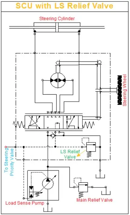
Steering Unit with Load Sense Relief Valve
Now, what I recommend is to check out the SCU manufacturer page which covers what are the latest technologies in the market. Like Danfoss Steering, Ognibene Steering or M+S Steering. Why I would recommend is, becuase this little thing make up your mind to learn more about steering or for highly professional it make them proud to say, “I know that” or “I’ve worked on that.”
Conclusion
In the world of big machinery like tractors, loaders and even autonomous vehicles – hydraulic steering systems have been the go to for years. At the heart of these systems is the Steering Control Unit (SCU) which directs hydraulic fluid to the wheels without the need for mechanical linkages making it very versatile and reliable across all applications.
From the components that make up the SCU – the gerotor assembly and control spool – to the various valves for protection and efficiency the hydraulic steering system is a finely tuned machine. Each valve whether it’s the inlet check valve to prevent kickback or the load sensing relief valve to manage excess pressure plays a big part in making the steering system smooth and safe.
Once you get into these systems you need to understand how they work, especially when it comes to servicing and troubleshooting. Whether you’re maintaining a tractor or working on more complex machinery a good understanding of how the SCU components work together will make all the difference.
What’s Next?
In this post, we covered the application of steering units and explored their key components (spool, sleeve, centering pin, etc.). We also looked at various design elements, including critical valves like the inlet check valve, port relief valve, and load-sensing relief valve.
🚀 Coming Up Next (Post 2):
In the next post, we will dive into the different types of hydraulic steering units—covering open center, power beyond, and closed center steering units. We will also explore the load sensing circuits and how static and dynamic signal systems impact steering performance. We will get to know how we can make a load sense system with a fixed displacement pump.
I hope you’ve picked up some new insights or at least refreshed your knowledge a bit. If you enjoyed this post, I’d really appreciate it if you could subscribe. I’m 100% planning to dive deep into hydraulics and break it down into simple terms for you!