
If you found this post through Part 1 of the series on hydraulic power pack design and sizing, you already know how to choose a pump, motor, and reservoir for your system. Now we get into one of the most underestimated components in any hydraulic power pack — the oil cooler.
Hydraulic systems are not 100% efficient. Every pump stroke, valve actuation, and pressure drop converts some input power into heat. That heat must go somewhere. If your system cannot dissipate heat fast enough, oil temperature climbs, viscosity drops, seals degrade, and you end up with expensive component failures — often without any warning.
In this post, we cover the complete process for hydraulic oil cooler sizing: from understanding why heat is generated, to working through three proven calculation methods, and finally selecting the correct cooler for a real-world 22 kW hydraulic power pack. We also show you the downloadable 3D SolidWorks model of the complete power pack so you can visualise the installation in your own environment.
Why Hydraulic Systems Always Generate Heat
Every hydraulic power pack produces heat as a by-product of inefficiency. This is not a design flaw — it is a physical reality. Gear pumps, piston pumps, directional control valves, and pressure relief valves all introduce losses. Those losses appear as heat in the hydraulic oil.
There are two strategies to deal with this heat:
- Passive cooling — rely on the surface area of the reservoir to radiate heat to the surrounding air. Works only for very small systems or very short duty cycles.
- Active cooling — route hot oil through an oil cooler (heat exchanger) where a fan forces air across fins, rapidly removing heat from the fluid.
Key Design Rule
The heat dissipation capacity of the system must be greater than or equal to the heat generated. If heat generated > heat dissipated, oil temperature will continue to rise until components fail.
For any hydraulic system with a motor above 2.2 kW operating continuously, passive cooling from the tank alone is almost never sufficient. You need an oil cooler.
When Is an Oil Cooler Required?
Not every hydraulic system needs an oil cooler. The requirement depends on duty cycle, ambient temperature, and tank size. Here is how to think about it:
Intermittent Duty Systems
These systems run for short bursts and rest long enough for the oil to cool naturally. If the heat generated during operation is less than or equal to what the tank can dissipate during idle, no cooler is needed. You can calculate this using the tank heat dissipation table later in this article.
Continuous Duty Systems
Systems that run for extended periods — typically more than 30 minutes without a significant rest — will accumulate heat faster than the tank can release it. In most industrial power packs, continuous duty plus a motor above 2.2 kW means an oil cooler is not optional.
Practical Rule of Thumb
If your motor is above 2.2 kW (3 HP) and your system runs continuously, compare heat generation against tank dissipation capacity before assuming no cooler is needed. In most cases above 5 kW, a cooler will be required.
Key Parameters for Oil Cooler Sizing
Before you can size an oil cooler, you must know the following parameters for your hydraulic power pack:
- Motor power (kW)
- Pump flow rate (LPM) — used to select the correct cooler from manufacturer flow curves
- Working pressure (bar)
- Tank capacity (litres)
- Maximum ambient temperature (°C) — the hottest day your system will ever see
- Maximum allowable oil temperature (°C) — typically 50–55°C for safe operation
- Pump type — fixed or variable displacement (affects heat generation estimate)
- Duty cycle — percentage of time the system is under load
A word on maximum oil temperature: studying the datasheets of most hydraulic component manufacturers — pumps, solenoid valves, proportional relief valves — you will find that nearly all are designed to tolerate 0°C to 60°C oil temperature. To build in a safety margin, we target a maximum design oil temperature of 50–55°C during sizing calculations.
Reference Data: Oil Properties and Tank Heat Dissipation
Hydraulic Oil Properties by ISO VG Grade
| ISO VG Grade | Density (kg/L) | Specific Heat (kJ/kg°C) | Specific Heat (kW·hr/kg°C) |
|---|---|---|---|
| VG 32 / 46 | 0.887 | 2.142 | 0.000594 |
| VG 68 / 100 | 0.847 | 2.130 | 0.000591 |
| VG 150 / 220 | 0.857 | 2.118 | 0.000588 |
| VG 320 / 460 / 680 | 0.857 | 2.118 | 0.000588 |
Heat Radiating Capacity of Hydraulic Reservoirs
The table below shows how much heat a bare steel reservoir can dissipate at various temperature differences between oil and ambient air. This is your passive cooling baseline before adding an oil cooler.
| Tank Capacity (L) | Tank Area (m²) | Temperature Difference (Oil Temp. to Ambient Air Temp.) | |||||||
|---|---|---|---|---|---|---|---|---|---|
| 10°C (kW) | 15°C (kW) | 20°C (kW) | 25°C (kW) | 30°C (kW) | 35°C (kW) | 40°C (kW) | 45°C (kW) | ||
| 40 | 1 | 0.14 | 0.22 | 0.29 | 0.36 | 0.43 | 0.51 | 0.58 | 0.65 |
| 55 | 1.2 | 0.17 | 0.26 | 0.35 | 0.48 | 0.52 | 0.61 | 0.69 | 0.78 |
| 75 | 1.3 | 0.19 | 0.28 | 0.38 | 0.47 | 0.56 | 0.66 | 0.75 | 0.85 |
| 110 | 1.5 | 0.22 | 0.33 | 0.43 | 0.54 | 0.65 | 0.76 | 0.87 | 0.98 |
| 150 | 2.3 | 0.33 | 0.50 | 0.66 | 0.83 | 1.00 | 1.16 | 1.33 | 1.50 |
| 200 | 2.7 | 0.39 | 0.59 | 0.78 | 0.98 | 1.17 | 1.37 | 1.56 | 1.76 |
| 225 | 2.9 | 0.42 | 0.63 | 0.84 | 1.05 | 1.26 | 1.47 | 1.68 | 1.89 |
| 300 | 3.7 | 0.53 | 0.80 | 1.07 | 1.34 | 1.60 | 1.87 | 2.14 | 2.41 |
| 380 | 4.4 | 0.64 | 0.95 | 1.27 | 1.59 | 1.91 | 2.23 | 2.54 | 2.86 |
| 450 | 4.9 | 0.71 | 1.06 | 1.42 | 1.77 | 2.12 | 2.48 | 2.83 | 3.19 |
| 570 | 5.2 | 0.75 | 1.13 | 1.50 | 1.88 | 2.25 | 2.63 | 3.01 | 3.38 |
| 750 | 6.5 | 0.94 | 1.41 | 1.88 | 2.35 | 2.82 | 3.29 | 3.76 | 4.23 |
Example read: A 200 L tank with oil at 55°C and ambient at 40°C (ΔT = 15°C) dissipates approximately 0.59 kW passively. For a 22 kW motor system generating 6.37 kW of heat, that 0.59 kW is clearly not enough — you need an active oil cooler.
Four Methods for Hydraulic Oil Cooler Sizing
There are four accepted methods for determining the required cooling capacity of an oil cooler. Each is suited to a different situation depending on what data you have available.
Method 1: Tank Oil Temperature Change Method
This method measures actual heat accumulation in the system under real operating conditions. It is the most accurate method when the machine is already installed and running.
How it works:
- Record the initial oil temperature at start-up.
- Record the oil temperature again every hour while the machine runs under normal load.
- Calculate the rate of temperature rise (°C per hour).
- From that rate, calculate the heat buildup rate in kW.
- Add a 10–20% safety factor, then express the result as a specific cooling requirement (Kr) in kcal/hr·°C.
Method 1 Formula
Heat Buildup (kW) = Tank Volume (L) × Specific Heat (kW·hr/kg°C) × Density (kg/L) × Temperature Rise (°C/hr) Kr (kcal/hr°C) = (Heat Buildup × 1.1 × 860) ÷ ΔT where ΔT = Max oil temp − Ambient temp
Example Calculation
System specifications:
- Oil tank volume: 200 liters (ISO VG 68 oil)
- Pump flow: 20 LPM
- Ambient air temperature: 40°C
- Maximum allowed oil temperature: 53°C
- Motor power: 2.2 kW
Step 1: Measure Temperature Rise
Max observed temperature increase, ΔT = 7°C over 1 hour
For ISO VG 68 oil (from reference data):
- Specific heat = 0.000591 kW·hr/kg°C
- Density = 0.847 kg/liter
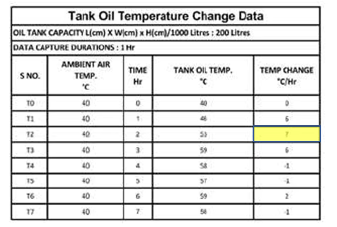
Tank Oil Temprature Change Data for 200 Liter Tank
Step 2: Calculate Heat Buildup
Heat buildup = Tank volume × Specific heat × Density × Temperature rise
= 200 × 0.000591 × 0.847 × 7 = 0.7 kW
Taking a safety factor of 10%:
Required heat dissipation = 1.1 × 0.7 = 0.77 kW
Step 3: Calculate Specific Cooling Requirement
Temperature difference available for cooling: = 53°C – 40°C = 13°C
Specific cooling required:
= 0.77 / 13 = 0.0592 kW/°C (at 20 LPM flow)
Step 4: Convert Units
Using: 1 kW = 860 kcal/hr
Required cooling capacity:
= 0.0592 × 860 = 50.94 kcal/hr°C
Step 5: Select Oil Cooler
From the manufacturer’s cooling curves, for 20LPM flow (datasheet):
- Model A → 38 kcal/hr°C ❌ (insufficient)
- Model B → 76 kcal/hr°C ✅ (meets requirement)
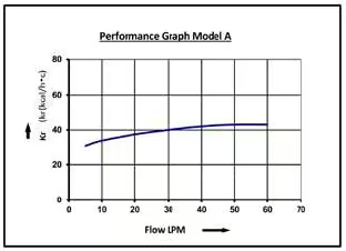
Model A Cooling Capacity
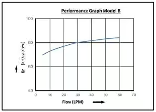
Model B Cooling Capacity
Method 2: Dissipated Heat Method
This method is ideal when you already have a working system with an oil cooler and want to size a replacement or verify adequacy. Measure oil temperature at the cooler inlet and outlet while the system is at steady state.
Method 2 Formula
Heat Dissipation (kW) = Flow per hour (L/hr) × Specific Heat × Density × (Tin − Tout) Flow per hour = Pump flow (LPM) × 60 Apply 10% safety factor, then calculate Kr.
Example Calculation
System specifications:
- Oil tank volume: 200 liters (ISO VG 68 oil)
- Pump flow: 20 LPM
- Ambient air temperature: 40°C
- Motor power: 2.2 kW
- Oil inlet temperature (Tin): 53°C
- Oil outlet temperature (Tout): 50°C
Step 1: Calculate Heat Dissipation
Heat Dissipation=Flow per hour × Specific heat × Density × (Tin−Tout)
Where:
- Flow per hour = 20 × 60 = 1200 L/hr
- Specific heat = 0.000591 kW·hr/kg°C
- Density = 0.847 kg/liter
- Temperature difference = 53 – 50 = 3°C
Heat Dissipation = 1200×0.000591×0.847×3 = 1.8kW = 1548kcal/hr
Taking 10% safety margin: 1.1×1548 = 1703 kcal/hr
Step 2: Calculate Specific Cooling Requirement
Available temperature difference, Delta T = 53 – 40 = 13°C
Kr = 1703/13 = 131 kcal/hr°C
Final Selection
We need to select an oil cooler from the manufacturer’s datasheet that provides:
👉 Kₙ ≥ 131 kcal/hr°C at 20 LPM flow
Using the manufacturer’s cooling curves (as discussed in Method 1), select a model that meets or exceeds this requirement.
Method 3: Cycle Time Analysis Method
The previous two methods provide accurate results but can be time-consuming and may not always be practical. In such cases, cycle time analysis offers a simpler and effective approach.
The key principle here is:
👉 Maximum heat is generated when the hydraulic system is pressurized but not doing useful work.
- When actuators (cylinders or motors) are performing work → less heat is generated
- When the system is pressurized without movement (idle under load) → most input power converts into heat
Approach
We calculate the percentage of time the system remains pressurized (or under load) during a cycle.
- If the system is pressurized for 50% of the time → 👉 Heat generation ≈ 50% of motor power
- If the system is continuously pressurized → 👉 Heat generation ≈ 100% of motor power
As with other methods, include a 10–20% safety margin.
Method 3 Formula
Heat Generated (kW) = Motor Power × (Pressurised Time ÷ Total Cycle Time) Kr (kcal/hr°C) = (Heat Generated × 1.1 × 860) ÷ (Max Oil Temp − Ambient Temp)
Example Calculation
System specifications:
- Oil tank volume: 200 liters (ISO VG 68 oil)
- Pump flow: 20 LPM
- Ambient air temperature: 40°C
- Motor power: 2.2 kW
Step 1: Determine Cycle Details
- Total cycle time = 5 minutes
- System pressurized time = 1.6 minutes
Fraction of time under load = 1.6/5 = 0.32
Step 2: Estimate Heat Generation
Heat generated = 2.2 * 0.32 = 0.704 kW
Taking 10% safety factor: 1.1 times 0.704 = 0.774 kW = 0.774 x 860 = 666 kcal/hr
Step 3: Calculate Specific Cooling Requirement
- Oil temperature = 53°C
- Ambient temperature = 40°C
- ΔT = 13°C
Kr = 666/13 = 51.23 kcal/hr°C
Final Selection
We need an oil cooler with: 👉 Kₙ ≥ 51.23 kcal/hr°C at 20 LPM flow
Refer to the manufacturer’s cooling curves and select the appropriate model that meets or exceeds this value.
💡 Practical Insight
- This method is quick and practical for field estimation
- Works best when cycle timing is known but temperature data isn’t available
- Slightly less accurate than measurement-based methods, but highly useful in real-world design stages
Method 4: Rule of Thumb Method
When none of the above three methods are practical — particularly at the early design stage — use this quick estimate based on pump type:
- Fixed displacement pump: Heat generation ≈ 30% of motor power
- Variable displacement pump: Heat generation ≈ 20% of motor power
Always validate rule-of-thumb results with detailed methods for critical applications. This approach is best used for initial selection and budget estimation.
Example Calculation
System specifications:
- Oil tank volume: 200 liters (ISO VG 68 oil)
- Pump flow: 20 LPM
- Ambient air temperature: 40°C
- Oil temperature: 53°C
- Motor power: 2.2 kW
Case 1: Fixed Displacement Pump
Estimated heat generation:
= 30% x 2.2 = 0.66 kW
Including 10% safety margin:
= 1.1 x 0.66 = 0.726 kW = 0.726 x 860 = 624 kcal/hr
Temperature difference, Delta T = 53 – 40 = 13°C
Specific cooling requirement: Kr = 624/13 = 48 kcal/hr°C
Case 2: Variable Displacement Pump
Estimated heat generation:
= 20% x 2.2 = 0.44 kW
Including 10% safety margin:
= 1.1 x 0.44 = 0.484 kW = 0.484 x 860 = 416 kcal/hr
Temperature difference, Delta T = 53 – 40 = 13°C
Specific cooling requirement: Kr = 416/13 = 32 kcal/hr°C
Final Recommendation, For this system (20 LPM flow):
- Fixed displacement pump: 👉 Select oil cooler with Kₙ ≥ 48 kcal/hr°C
- Variable displacement pump: 👉 Select oil cooler with Kₙ ≥ 32 kcal/hr°C
Refer to the manufacturer’s cooling curves (as discussed in Method 1) to select the appropriate model.
💡 Practical Insight
- This method is quick and easy, ideal for early-stage design or rough estimation
- Less accurate than measurement-based methods, but widely used in industry
- Always validate with detailed methods for critical applications
Pratical Example: Sizing the Cooler for a 22 kW Hydraulic Power Pack
Let us walk through the complete cooler selection calculation for the 22 kW power pack that is the subject of the downloadable 3D SolidWorks model in this post.
Power Pack Specifications
| Parameter | Value | Unit |
|---|---|---|
| Motor Power | 22 | kW |
| Motor Speed | 1475 | RPM |
| Motor Voltage | 380 | V |
| Pump Displacement | 40 | cc/rev |
| Pump Flow Rate | 56.05 | LPM |
| Pump Volumetric Efficiency | 0.95 | — |
| Tank Volume | 200 | Litres |
| Max. Ambient Temperature | 49 | °C |
| Max. Oil Temperature | 55 | °C |
| Tank Heat Dissipation | 0.234 | kW |
Step 1: Estimate Heat Generation (Rule of Thumb — Fixed Displacement Pump)
Heat generation = 30% of motor power = 0.30 × 22 kW = 6.6 kW
Step 2: Check Tank Heat Dissipation Capacity
For a 200 L tank at ΔT = 55°C − 49°C = 6°C. From the reference table at ΔT = 6°C, a 200 L tank dissipates 0.234 kW. But our heat generation is 6.6 kW. The tank alone cannot keep up.
Excess heat requiring active cooling = 6.6 − 0.234 = 6.366 kW
Step 3: Apply Safety Factor
Apply 10% safety margin to the cooling requirement:
Required cooling = 6.366 × 1.1 = 7 kW = 7 × 860 = 6,022.24 kcal/hr
Step 4: Calculate Specific Cooling Requirement (Kr)
Temperature difference available for cooling = Max oil temp − Ambient temp = 55°C − 49°C = 6°C
So, Cooling Requirement = 6022.24/6 = 1003.706 kcal/hr°C
Final Selection
Required Kr = 1,003.7 kcal/hr·°C at 56 LPM. From the manufacturer’s cooling performance curves, the AH1680 air-blast oil cooler meets this requirement at the design flow rate. This is the model included in the downloadable 3D power pack model below.
3D SolidWorks Model
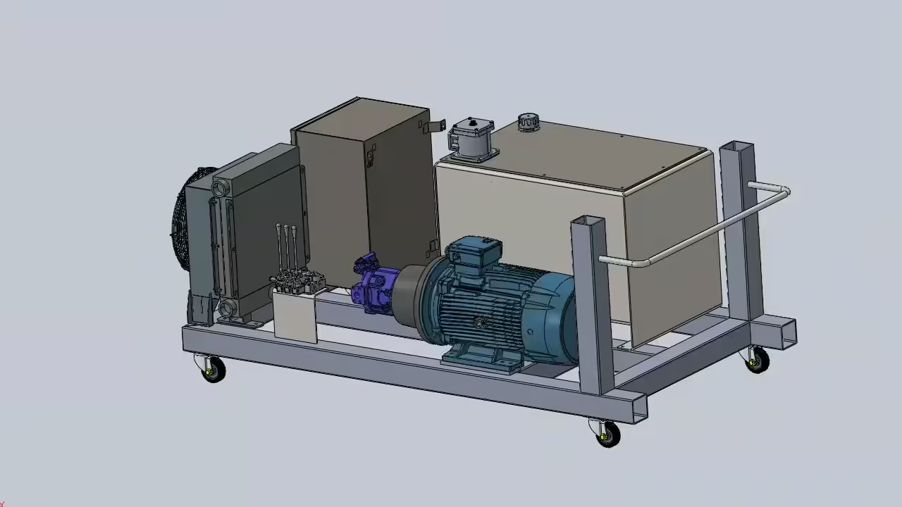
🔩 Download the 3D SolidWorks Model — Complete 22 kW Hydraulic Power Pack
The SolidWorks assembly includes all components sized in this post:
- Electric Motor — 22 kW, 1475 RPM (YE2-180L-4)
- Hydraulic Pump — 40 cc fixed displacement
- Hydraulic Tank — 200 L reservoir
- Air-Blast Oil Cooler — AH1680 (sized for 55°C ambient, 56 LPM)
👉 Get the model here: epichydraulic.gumroad.com/l/ylrygy
Want to design your complete hydraulic power pack from A to Z?
If you need a practical, reliable calculation for your specific application — motor sizing, pump selection, tank sizing, cooler selection, and full circuit design — we can help. Reach out at info@epichydraulic.com, or fill out the form and we will get back to you.
Oil Cooler Installation: Location, Mounting, and Flow Rate
Selecting the right oil cooler model is only half the job. Where and how you install it determines whether it actually performs to spec.
Choosing the Installation Location
- Position the cooler where ambient airflow is unrestricted. Avoid recirculation zones where hot exhaust air from the cooler fan can be drawn back in — this reduces effective cooling capacity significantly.
- Ensure the cooler is reachable for cleaning. Fins clog with dust and debris over time. A blocked cooler can lose 30–50% of its rated capacity.
- Minimise vibration at the mounting point. Coolers have thin aluminium fins and brazed connections — sustained vibration causes fatigue cracking and leaks.
Mounting Orientation
Most manufacturers recommend vertical mounting for natural convection assistance. If horizontal mounting is unavoidable, confirm with the datasheet that the model supports it without oil pooling in the core.
Flow Rate Matching
Never exceed the cooler’s rated maximum flow rate. Excessive flow reduces residence time in the core, cutting heat transfer efficiency. Insufficient flow causes localised hot spots. For the AH1680 selected here, the design flow is 56 LPM — always verify against the manufacturer’s performance curves at your actual flow rate.
Oil Cooler Troubleshooting: Common Problems and Solutions
| Problem | Likely Cause | Corrective Action |
|---|---|---|
| Oil overheating despite cooler | Cooler fins blocked with debris; cooler undersized; ambient higher than design | Clean fins; verify Kr at actual flow; check ambient vs design value |
| Oil too cold in winter | Cooler too large; no bypass valve fitted | Install thermostatic bypass valve to maintain minimum oil temp |
| Oil leaking from cooler | Vibration fatigue; over-pressure event; corrosion | Check mounting dampers; verify relief valve setting; replace cooler core |
| Fan motor failure | Overload due to restricted airflow; electrical fault | Clear air inlet/outlet; check motor current against nameplate |
| Noisy fan / vibration | Debris in fan blades; worn fan bearing | Clear blades; replace bearing or complete fan assembly |
Conclusion
Hydraulic oil cooler sizing is not complicated once you understand the underlying heat balance. The core principle is simple: if your system generates more heat than it can dissipate, oil temperature rises until something fails. The goal of every sizing calculation is to select a cooler that closes that gap — with enough margin to handle the worst-case ambient conditions your system will face.
For the 22 kW power pack detailed in this post, the AH1680 air-blast oil cooler was selected to handle a heat generation rate of 6.37 kW at 56 LPM pump flow, operating in a 55°C maximum ambient environment. The complete design — with all component selections verified — is available as a downloadable SolidWorks 3D assembly.
Whether you use the rule of thumb for a quick estimate or work through the temperature change method for a critical application, the four sizing methods in this article give you a structured approach that mirrors how experienced hydraulic engineers solve this problem in the field.
Ready to size your oil cooler? Use these resources:
- Download the 22 kW SolidWorks 3D Power Pack Assembly → epichydraulic.gumroad.com/l/ylrygy
- Read Part 1: Power Pack Design & Sizing → epichydraulic.com/hydraulic-power-pack-configuration-guide/
- Browse all hydraulic engineering guides → epichydraulic.com