Last updated on June 8th, 2025 at 02:31 pm
In large off-road machines, a Steering Control Unit (SCU) alone may not be sufficient to supply the required hydraulic flow for steering.
As machine size increases, so do the steering cylinder dimensions, which demand higher oil flow rates to operate efficiently.
To meet this demand, hydraulic steering amplifiers are used to increase the flow supplied by the SCU, ensuring smooth and responsive steering even for massive machines.
Why Are Steering Amplifiers Needed?
- The flow rate from a standard SCU is often too low for large vehicles.
- Steering amplifiers multiply the input flow to achieve the required displacement in the steering cylinders.
- This is especially useful in heavy-duty applications like mining trucks and large ships, where steering lag or inefficiency can severely impact maneuverability.
- For example, Danfoss steering amplifiers offer magnification factors ranging from 4x to 20x, significantly boosting steering performance.

A Caterpillar 797B haul truck parked on a mining site, with two people standing next to it, showcasing the truck’s massive size.
OSQ Flow Amplifier
For very heavy vehicles such as large forklifts, loaders, dumpers, and special-purpose vehicles exceeding 100 tons, Danfoss OSQ flow amplifiers provide a high-capacity solution for steering flow amplification. The OSQ Flow Amplifier operates on the load-sensing principle, ensuring that steering always gets the priority flow it needs before any other hydraulic functions receive oil.
OSQ Variants
Danfoss offers two versions of the OSQ flow amplifier.
OSQA: Designed for standard fittings
OSQB: Includes a back pressure valve in the tank connection and supports flange-type fittings.
The steering response is proportional to the rate at which the steering wheel is rotated. Faster steering wheel rotation = more oil flow amplification = quicker steering response.
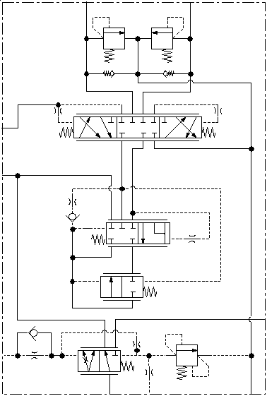
OSQA type Steering Amplifier
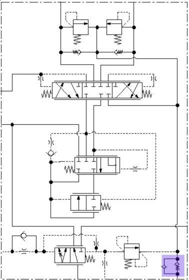
OSQB type Steering Amplifier
Data of OSQ Flow-Amplifier
- Amplification Factors: 4, 5, 8, 10 or 20
- Steering System Displacement: 640 – 4160 cm³/rev (39 – 254 in³/rev)
- Maximum Steering Pressure: 240 bar (3480 psi)
- Flow Capacity:
- OSQA: 240 l/min
- OSQB: 400 l/min
One of the key safety features of the OSQA and OSQB amplifiers is their ability to revert to manual steering in the event of a pump failure or hydraulic system malfunction. In this mode, the amplifier stops amplifying oil flow, and the steering unit functions as a manual pump, providing temporary control until hydraulic assistance is restored.
Since the system relies solely on human effort, steering a large machine requires significantly greater effort from the operator. Manual steering remains possible but is limited. Under normal operation, the maximum torque required to turn the steering wheel does not exceed 5 N•m
Operation of the Hydraulic Steering Amplifier
In this system, the Steering Control Unit (SCU) functions similarly to a pilot controller, directing pilot oil to the steering amplifier valve assembly instead of sending oil directly to the steering cylinders. The SCU regulates the oil flow based on how fast the steering wheel is turned.
Inside the steering amplifier, a directional valve is pilot-operated by the SCU and performs two key tasks:
- Amplifies Oil Flow – It takes steering oil from the SCU and sends it to the flow-combiner valve, which mixes this flow with oil from the steering pump and accumulator circuit, increasing the total available oil flow.
- Directs the Amplified Flow – It sends the amplified oil to the correct steering cylinder port, ensuring the machine turns in the intended direction.
The flow-combiner valve and flow check valve inside the amplifier work together to boost the oil flow before directing it through the amplifier’s directional valve.
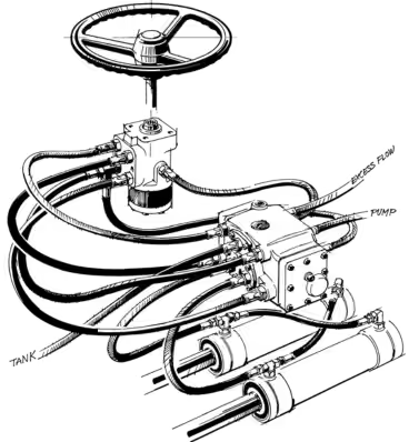
Steering Amplifier Line Connection with Steering Unit
Steering Modes
Neutral Position (No Steering Input)
- When the steering wheel is stationary, the control spool (G) remains in place.
- Oil from the steering pump (A) enters the priority valve (HP port) of the flow amplifier.
- The inlet pressure moves spool (D) to the right, directing almost all pump flow to the loader system (main control valve) through the EF port.
- A small amount of oil flows into the hydraulic tank via control spool (D) to prevent thermal shock in the steering unit.
Left Turn Operation
- Steering wheel turned left → Spool (G) shifts right within the steering unit.
- Oil from the pump (A) enters the HP port of the flow amplifier.
- Oil passes through the priority valve spool (D) inside the flow amplifier.
- The priority spool (D) adjusts its position based on the pressure difference across the main orifice, balanced by the control spring (K).
- Oil from the steering unit, combined with additional oil from the priority valve spool (D), is directed to the amplifier spool (M).
- The amplified oil flow is then sent to:
- The small chamber of the left steering cylinder.
- The large chamber of the right steering cylinder.
- Return oil from the cylinders flows back to the hydraulic tank via the directional spool (J) of the flow amplifier (6).
- The machine turns left.
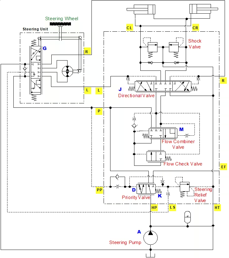
Flow Amplifier Schematic
Right Turn Operation
- Steering wheel turned right → Spool (G) shifts left within the steering unit.
- Oil from the pump (A) enters the HP port of the flow amplifier.
- Oil passes through the priority valve spool (D) inside the flow amplifier.
- The priority spool (D) adjusts its position based on the pressure difference across the main orifice, balanced by the control spring (K).
- Oil from the steering unit, combined with additional oil from the priority valve spool (D), is directed to the amplifier spool (M).
- The amplified oil flow is then sent to:
- The small chamber of the right steering cylinder.
- The large chamber of the left steering cylinder.
- Return oil from the cylinders flows back to the hydraulic tank via the directional spool (J) of the flow amplifier.
- The machine turns right.
LunchBox Sessions explained amplifier operation in a very understandable way.
Components of the Flow Amplifier
I have added flow arrows next to each port for your reference and highlighted unique components in different colors.
Housing: The main body that houses all internal components of the flow amplifier.
Shock Valve and Suction Valve: Shock Valve protects the flow amplifier from pressure shocks caused by external forces acting on the steering cylinders. It limits maximum pressure drop from CL to HT and CR to HT to prevent damage. Suction Valve ensures oil suction on the side of the steering cylinder pistons, where cavitation might occur under unfavorable conditions.
Back Pressure Valve: Helps maintain optimal pressure within the system, preventing sudden drops that could affect performance.
Directional Spool: Directs the amplified oil flow to either CL or CR port, depending on the steering direction.
Pilot Pressure Relief Valve: Regulates pilot pressure within safe limits, ensuring stable operation and preventing overloading.
Priority Valve: Used in load sensing systems, where a single pump supplies oil to both the steering system and working hydraulics. It ensures the steering system always has priority over other hydraulic functions. When the steering unit is in neutral, the LS (Load Sensing) connection pressure remains close to zero.
Amplification Valve: Increases oil flow from the steering unit before sending it to the steering cylinders. It ensures that the amplified flow is proportional to the rate of steering wheel rotation.
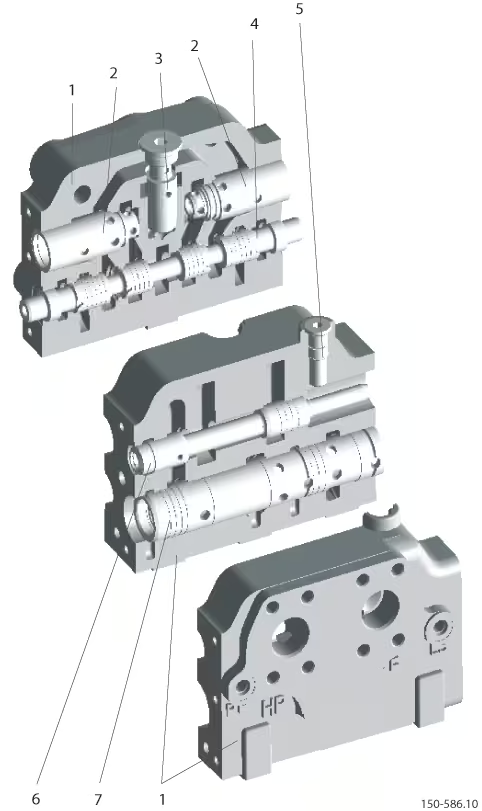
Components of Danfoss’s OSQB Amplifier
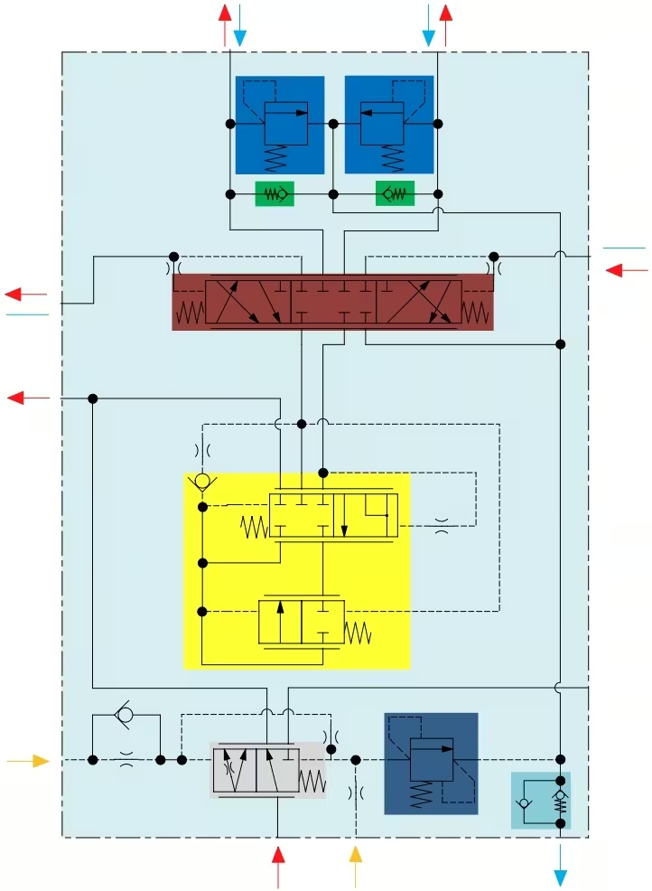
Amplifier Componets in Colour Highlighted
Calculation for Flow-Amplifier
Amplification Factor
Symbols:
- V (cm³) → Stroke volume
- i (rev) → Required number of steering wheel revolutions (lock to lock)
- Vv (cm³/rev) → Steering unit displacement
- f → Amplification factor of the flow-amplifier
Formula for Steering Unit Displacement and Amplification Factor:
Vv × f = V / i
Pump Flow Calculation
Symbols:
- Q (l/min) → Oil flow required for steering components
- QA (l/min) → Oil flow required for working hydraulics
- QP (l/min) → Total oil flow required from the pump
- Vv (cm³) → Steering unit displacement
- f → Amplification factor of the flow-amplifier
- n (rev/min) → Required steering speed
Formula for Steering Oil Flow Requirement:
Q = Vv × f × n × 10⁻³
Pump Flow Requirement
If hydraulics and steering do not operate together:
QP = max(Q, QA)
If hydraulics and steering operate together:
QP = QA + Q
Conclusion
In large off-road machines, the Steering Control Unit (SCU) alone often can’t provide enough hydraulic flow for steering. As machine size increases, so do the steering cylinder dimensions, requiring more oil flow for smooth operation. To solve this, hydraulic steering amplifiers boost the flow, making steering more responsive and efficient.
Danfoss OSQ flow amplifiers are commonly used in heavy vehicles like mining trucks, loaders, and forklifts. These amplifiers operate on a load-sensing principle, ensuring the steering system always gets priority oil flow. There are two main variants—OSQA for standard fittings and OSQB which offer amplification factors from 4x to 20x, significantly improving steering performance.
The amplifiers work by taking oil from the SCU and mixing it with additional oil from the pump, increasing the total flow before directing it to the steering cylinders. By understanding the function, components, and calculations behind steering amplifiers, engineers can optimize steering systems for heavy machinery, improving control, efficiency, and safety.
What’s Next?
So far in our steering series, we have covered:
Post 1: The applications of steering units, along with a deep dive into their components (spool, sleeve, centering pin, etc.) and design elements (various valves like inlet check, port relief, and load-sensing relief valves).
Post 2: A breakdown of different types of steering units, including open center, power beyond, and closed center steering units. We also explored load sensing circuits and their static/dynamic signal systems.
Post 3: Analyzed steering work circuits, covering reaction vs. non-reaction steering. We also discussed advanced features like 2-speed technology, Q-Amp flow amplification, wide angle steering, and cylinder dampening—along with their applications.
Post 4: A Detailed focus on the steering control unit’s spool-sleeve mechanism. Steering unit operates in different modes, including 4-wheel steer, crab mode, and 2-wheel steer mode.
🚀 Coming Up Next (Post 6):
Now that we understand how steering amplifiers enhance hydraulic flow, the next post is about different types of off-road steering systems. We’ll cover Ackerman steering, articulated steering, hydrostatic steering, and combination systems. Their working mechanisms, applications, and advantages.
If you enjoyed this post, I’d really appreciate it if you could subscribe. I’m 100% planning to dive deep into hydraulics and break it down into simple terms for you!
