Last updated on June 8th, 2025 at 02:31 pm
Alright! In the first post on steering, we explored the components of a steering system and its design. This time, we’re diving into the different types of steering units like open center, closed center, and load-sensing systems.
I initially planned to include features within this post, but the detailed breakdown of the types of steering made this post longer than expected. So, for now, we’ll focus solely on the types of steering units. In Part 3, I’ll cover the features which can be added to steering unit and how the sleeve and spool operate when you steer. Stay tuned, and let’s get started!
Types of Steering Units
Just like implement circuit’s valves, steering units can also be open center, close center or load sense. Let’s brush up each types one by one.
Open Center Hydraulic Steering Unit
Similar to an open-center system, an Open Center Steering Unit allows the oil from the hydraulic pump to reservoir when it’s in the neutral position.
Fig. 1 shows schematic of open center SCU in the neutral position.
Fig. 2 shows schematic of open center SCU in the active position.
When the operator turns the wheel, the control spool, sleeve assembly, and gerotor move in sync, directing oil to steer the vehicle.
As shown in figure 2, as the operator rotates the steering wheel to the left, the SCU control spool/sleeve assembly directs the oil in and out of the SCU to steer the tractor to the left because oil pressure forces the steering cylinder piston to the right end of it’s cylinder.
This type of steering system has a simple and economical setup which often can be found in lawn equipment and utility vehicles.
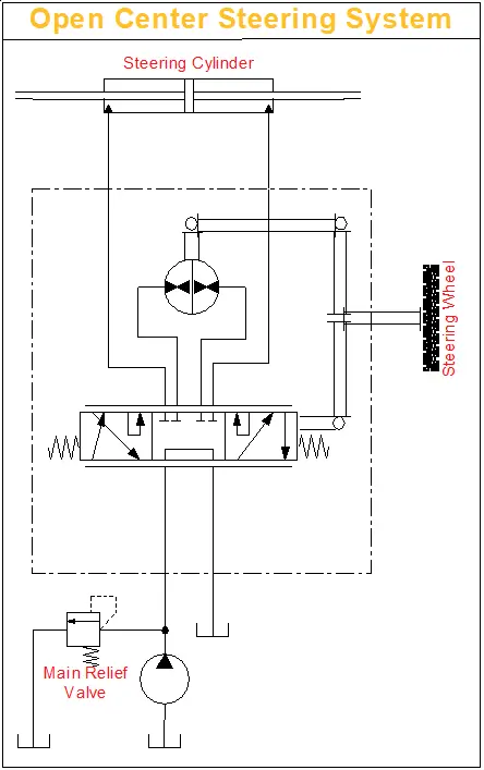
Fig. 1: Open Center Steering System in Neutral Position
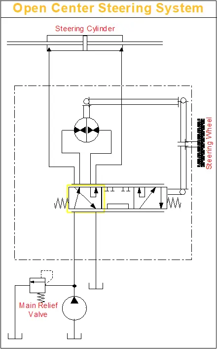
Fig. 2: Open Center Steering System in Active Position
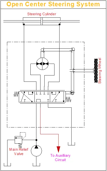
Fig. 3: Open Center Steering System with Power Beyond Port in Neutral Position
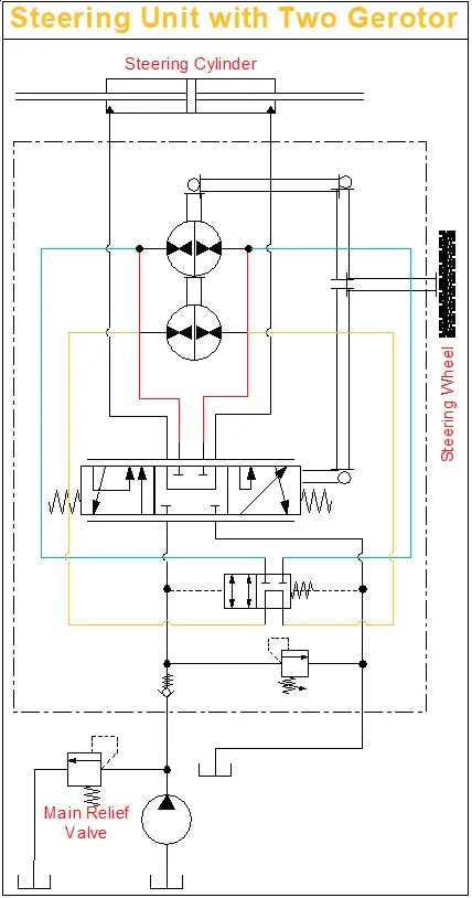
Fig. 4: Steering Unit with Two Gerotor
Open Center Power Beyond Hydraulic Steering Unit
Similar to the power beyond feature in implement systems, SCU which has power beyond inbuilt, directs flow to auxiliary systems when not steering. Once steering starts, it prioritizes flow for steering while directing the remaining flow to the auxiliary circuit.
The tank port of the steering unit has flow only when steering is operated. Thus, flow out of the auxiliary (“PB”) port and the tank port will fluctuate or stop depending on steering input.
It’s crucial to avoid constant flow to auxiliary functions while steering and ensure auxiliary valves are open center types. However, when auxiliary functions are operated during steering, you might feel a slight bump in steering.
The following special considerations should be addressed when applying power beyond steering
- Auxiliary valves (connected to PB) must be open center type.
- Flow is only directed to the tank port when steering is operated. Avoid systems where return flow from tank port is used for auxiliary functions.
- Inlet pressure to the steering unit will be the higher of steering system pressure or auxiliary valve pressure.
Applications
- Lawn and Garden Equipment
- Utility Vehicles
Close Center Non Load Sensing Steering Unit
Similar to a close-center system, in Close Center Steering Unit pump and reservoir are disconnected when it’s in the neutral position.
As shown in Fig. 5, a closed center non load sensing SCU would be used with a pressure-compensating hydraulic system, but this setup has become rare as most of the SCUs are used with load-sensing priority valves.
This type of Steering units is possible to observe Thermal Shock condition when the hydraulic system has operated for some time without turning the steering wheel, causing the fluid in reservoir and system to heat up while the steering unit is relatively cool .
If steering wheel is turned very quickly, due to thermal Shock, then it is possible to experience temporary seizure and have the internal parts of the steering unit damaged. The temporary seizure may be followed by a total free wheeling. To avoid this thermal shock, P and T ports are connected via a orifice (called- bleed orifice). This makes steering to kind of sense the temperature and avoid any seizure.
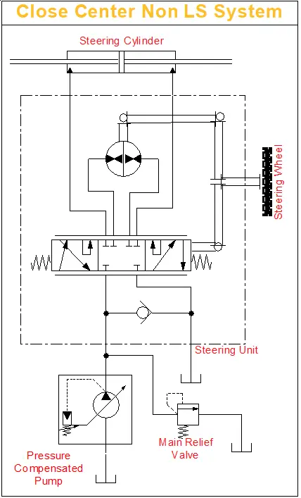
Fig. 5: Close Center Non Load Sense Steering System
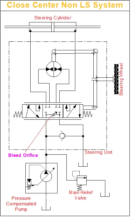
Fig. 6: Close Center Non Load Sense Steering System with Neutral Bleed
Neutral Bleed Feature
Closed Center Steering Control Units are available with and without neutral bleed feature. Most applications may not require the bleed feature, however, the maximum temperature differential between components within the steering circuit must not exceed specification (50° F or 28° C). If the temperature differential exceed this limit then it is required to use SCU with a bleed feature.
As shown in Fig. 6, the neutral bleed feature allows a small flow of fluid to pass through the unit when in neutral to reduce the thermal differential.
Typical applications where neutral bleed is required are:
- Remote steering position from power source.
- Extended engine idle operation when vehicle is parked.
- High duty cycle operation sharing a common reservoir with the steering circuit.
Applications for this SCUs is generally a larger construction equipment.
Close Center Load Sensing Steering Unit
An open center or closed center SCU is a four-way DCV that has four ports: Inlet, Outlet, Right steer and Left steer.
A closed center load sensing SCU has an addtional fifth hydraulic, which is the load-sensing signal line.
This style of load sensing SCU is used in multiple types of hydraulic systems, such as:
- Open Center Hydraulic System (Fig. 7)
- Do note that, flow from EF port of Priority Valve goes to open center valve, which has P to T connected in neutral.
- If flow from EF port goes to close center valve, while keeping fixed displacement pump, then this situtation could make high load on engine
- Pressure Compensating Hydraulic System (Fig. 5 & 6)
- Load Sensing Pressure Compensating Hydraulic System (Fig. 8)
- Flow Sharing Hydraulic System
Using a load sensing steering unit with a priority valve in a power steering system offers several benefits:
- It ensures smooth, pressure-compensated steering, so variations in load don’t affect axle response or steering speed.
- It enables a true power beyond system by splitting the flow into two independent circuits.
- It isolates pressure spikes in each circuit, sending only the necessary flow to the steering circuit while allowing any extra flow to the auxiliary circuits.
- It guarantees reliable operation, as the steering circuit always gets flow and pressure priority.
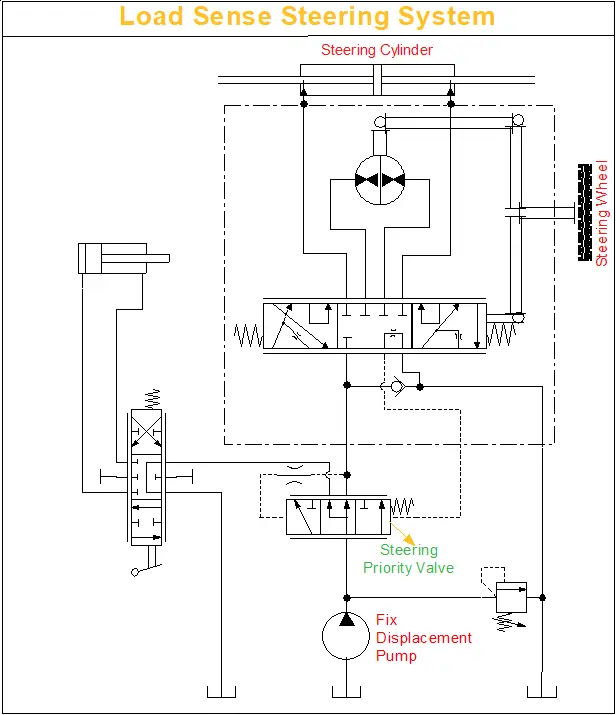
Fig. 7: Load Sense Steering System with Fixed Displacement Pump
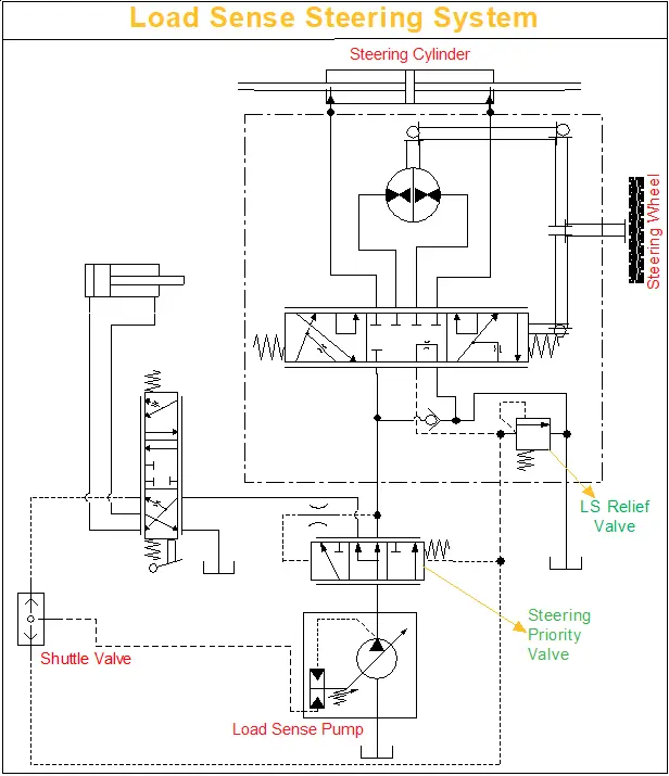
Fig. 8: Load Sense Steering System with Pressure & Flow Compensated Pump
Load Sensing Circuits : Signal Systems
Steering priority circuits often use one of two types of signal line configurations, either a static load-sensing signal or a dynamic load-sensing signal.
The static load-sensing signal is the standard type of signal configuration.
In a static signal system
The sense flow goes from the steering orbital to the priority valve.
When SCU is neutral, the sense flow vents to tank through the steering orbital. So, oil in the signal circuit is not flowing while the SCU is in a neutral position.
When SCU is active, the sense flow goes from the steering orbital to the priority valve.
As seen from Fig. 9, load sensing static steering systems have no oil flow in the LS connection when the steering unit is in neutral position.
Static load-sensing signal circuit is used when the steering system has sufficient steering performance, does not lack response, and the steering load-sensing signal lines are relatively short (less than six feet).
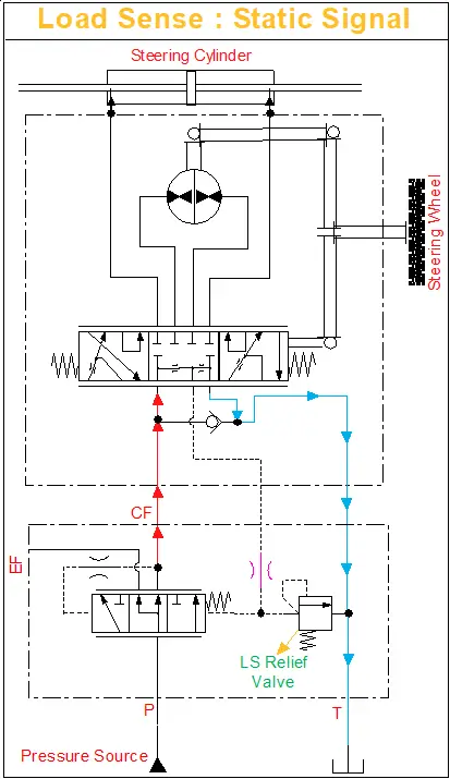
Fig. 9: Static Load Sense Signal during Neutral
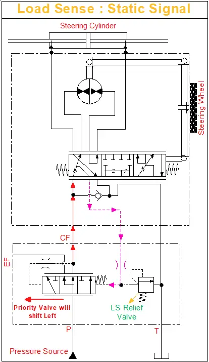
Fig. 10: Static Load Sense Signal during Active
In a dynamic signal system
The sense flow goes from the priority valve to the steering orbital.
When the SCU is neutral, the priority valve lets a small amount of oil flow vents to tank through an adjustable and bleed orifice in the orbital.
As seen from Fig. 11, load sensing dynamic steering systems have a constant oil flow in the LS connection in the direction of the steering unit even when the steering unit is in neutral position.
The dynamic L.S. priority valves have two orifices in the spool, one for damping (PP), and the other for feeding (DS) oil to the orbital.
When Orbitral is actuated as shown in Fig. 12, Pressure from ‘CF Port-Orbitral-Priority Valve (Red Arrow)’ takes over than ‘DS Orifice of Priority Valve-Orbitral (Orange Arrow)’ resulting pushing the Priority Valve to the left, allowing more flow to orbitral.
Turning the steering wheel opens the work ports and closes the bleed-off orifice, thus building pressure in the sense line pushing on the Priority Valve spool. This directs more oil to the orbital the faster you spin the wheel.
The dynamic flow of oil in the signal line generates a constant steering signal pressure, for example 50 to 150 psi, any time the tractor is running. Due to these benefits, most of the steering circuits uses a Dynamic Setup.
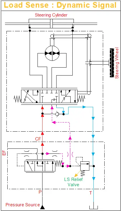
Fig. 11: Dynamic Load Sense Signal during Neutral
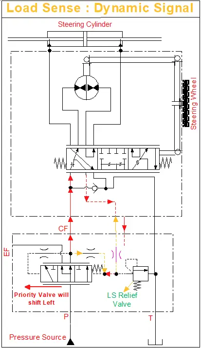
Fig. 12: Dynamic Load Sense Signal during Active
Engineers select dynamic load-sensing signal circuit when the machine’s signal line is longer than six feet, or the steering operation is unstable and inconsistent or gets delayed. Because this circuit enhances hydraulic steering responsiveness and helps warm up the circuit in cold climates and also gives a quick response to operator commands.
Conclusion
In this article we covered open center, closed center and load sensing hydraulic steering units. Knowing the difference is important as each has its own applications and benefits from simple and economical for small utility vehicles to load sensing. Now you know which steering unit is right for your equipment.
What’s Next?
So far in our steering series, we have covered:
Post 1:
We discussed the application of steering units, their key components (spool, sleeve, centering pin, etc.), and design elements like inlet check valves, port relief valves, and load-sensing relief valves.
🚀 Coming Up Next (Post 3):
We will examine steering work circuits, covering reaction vs. non-reaction steering. We will also discuss advanced steering features, including 2-speed technology, Q-Amp flow amplification, wide angle steering, and cylinder dampening, along with their advantages and applications.
If you enjoyed this post, I’d really appreciate it if you could subscribe. I’m 100% planning to dive deep into hydraulics and break it down into simple terms for you!
