Last updated on June 8th, 2025 at 02:31 pm
The spool and sleeve mechanism in a hydraulic steering unit plays a key role in directing oil flow to the steering cylinder, ensuring smooth and precise control based on the driver’s input.
When the driver turns the wheel left or right, the spool shifts within the sleeve.
This movement opens specific flow paths that allow pressurized oil to reach the correct cylinder port, generating the hydraulic force needed to move the steering cylinder. As the cylinder moves, it translates hydraulic pressure into mechanical motion, turning the wheels accordingly. This process provides the driver with responsive and consistent steering control.
The spool and sleeve mechanism is essential for regulating fluid direction and maintaining smooth operation. Its precise design enables accurate control whether the system is centered or in motion, and understanding its function helps in diagnosing problems like steering lag, free play, or uneven response.
In this post, we’ll go step by step through the spool and sleeve mechanism, exploring its role in flow control during neutral, left turns, and right turns. But, before going into the details, let’s quickly revisit the internal components of the steering unit, as covered in Post 1.
Key Components of the Orbitrol Valve
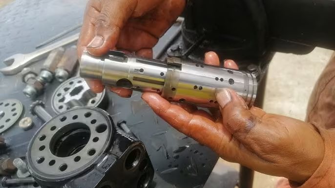
Sleeve and Spool for Steering Unit
The Steering Control Unit (SCU) is an essential component in hydraulic steering systems, such as those used in tractors. As discussed in Part 1 of Steering Series, it performs two main functions: Controls the direction of oil flow and Controls the quantity of oil flow.
The steering wheel’s drive shaft is splined to the control spool.
A centering pin and springs link the control spool to the control sleeve.
The pin fits loosely in the spool but tightly in the sleeve, ensuring the sleeve follows the spool when turning.
When the wheel stops, the centering springs return the spool/sleeve assembly to the center.
As the assembly turns, the centering pin rotates the drive shaft, which spins the internal gerotor within the gerotor assembly.
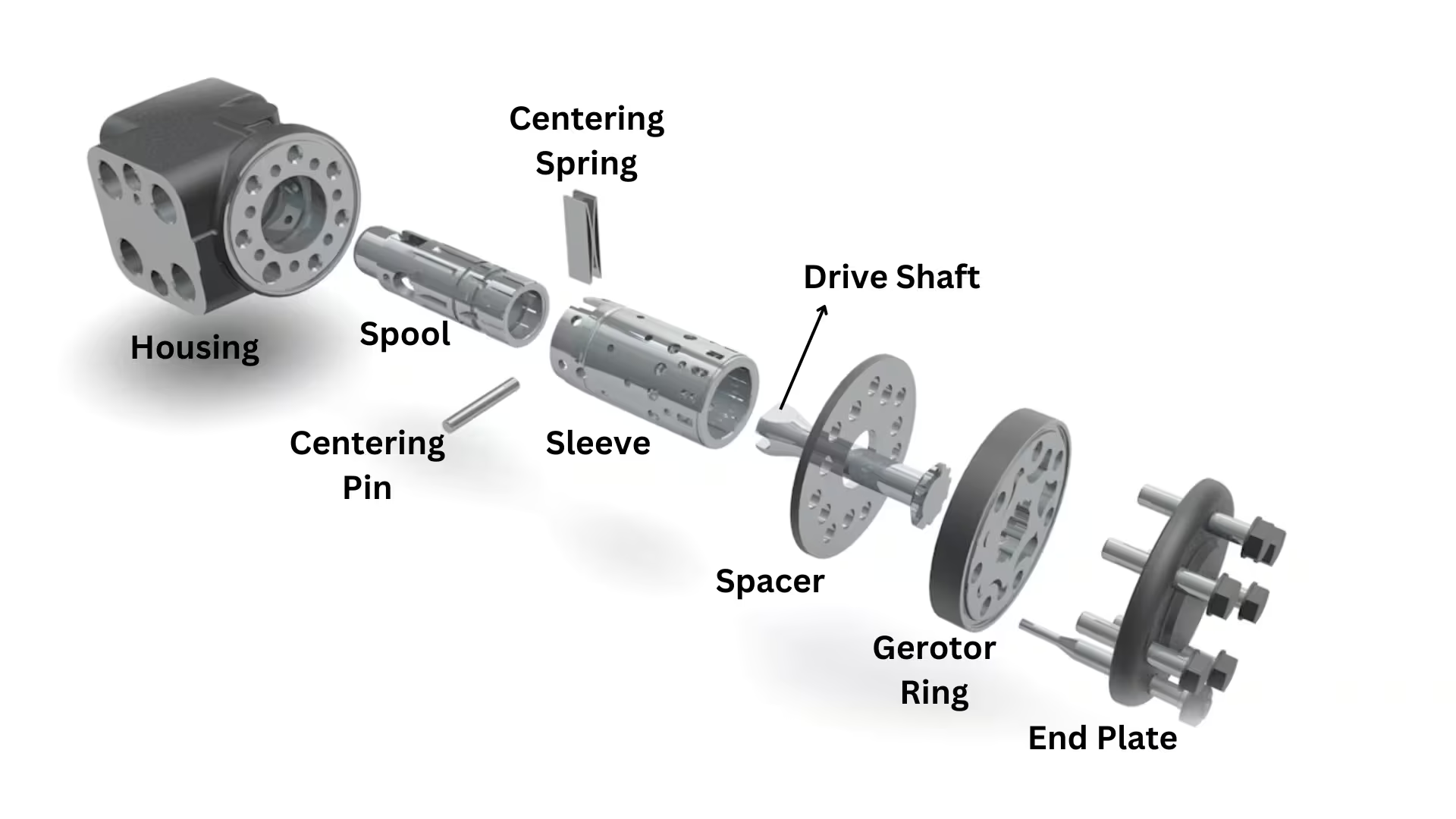
Steering Unit
Basic Steering Control Unit Mechanism
A. Input from Steering Wheel to Hydraulic System
When the steering wheel is turned, its drive shaft rotates.
The drive shaft is splined to the control spool, which starts moving as well.
The control spool is connected to the control sleeve via a centering pin and centering springs.
The centering pin fits loosely inside the control spool but tightly inside the control sleeve, ensuring that the sleeve follows the spool’s movement.
As the steering wheel turns, the control spool and control sleeve rotate, opening oil flow passages.
B. Oil Flow Control and Steering
The SCU housing, control spool, and control sleeve together function as a rotary directional control valve (DCV).
Based on the rotation direction Oil is directed to the right or left chamber of the steering cylinder.
The amount of oil flow determines the speed of wheel movement (faster wheel turn = more oil flow).
C. Returning to Neutral
When the steering wheel stops turning, the centering springs return the control spool and sleeve to their center position.
This action stops oil flow, and the wheels hold their position until another steering input is given.
Steering Unit Operation in Different Modes
We will examine the Danfoss OSPC Steering Unit with a priority valve used in a four-wheel steering (4WS) system. Understanding 4WS makes it easier to grasp two-wheel steering (2WS) since 4WS simply adds another layer of control.
In a 4WS system, a steer mode control valve is introduced to manage the rear-wheel steering. This valve can be electronically activated using a solenoid. Machines can be equipped with 2WS (Front-wheel steering only) or 4WS (Front and rear wheels steer together). If a machine supports both modes, the steer mode control valve enables switching between them.
How oil flow in Steering circuit
- In 4WS mode, oil from the steering unit first flows through the steer mode control valve, then to the rear steering cylinder, and finally to the front steering cylinder. This setup reduces the turning radius, improving maneuverability.
- To switch to 2WS mode, the first solenoid is activated. This diverts the oil flow directly from the steer mode control valve to the front steering cylinder, disabling rear-wheel steering.
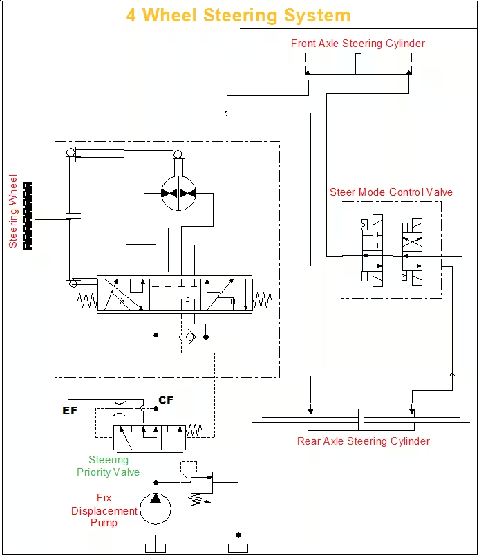
4WS Schematic
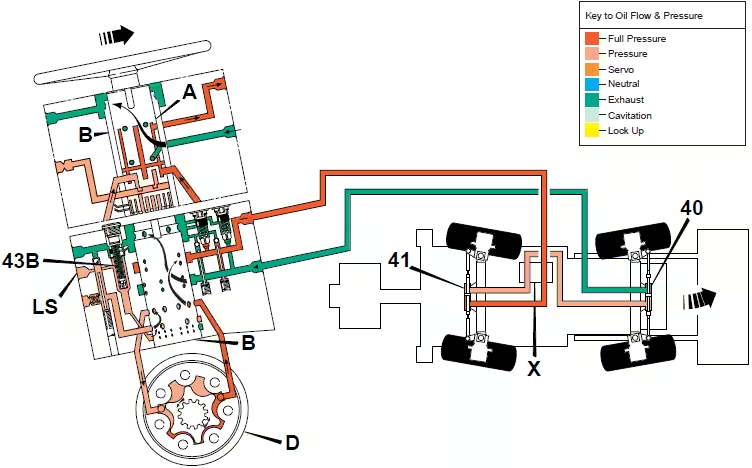
4 Wheel Steer Mode – Neutral
In the neutral position, hydraulic flow enters the steering unit through the bottom right-hand port, passing through the non-return valve (43C). Since the steering wheel is stationary, the inner spool (A) and sleeve (B) remain centered, held in place by the centering springs (K). Although Illustration shows flow in a single steering unit
- Pink Highlight – Flow passing through the sleeve to the spool.
- Lavender Highlight – Flow moving through the external surrounding components of the spool-sleeve assembly and then into the gerotor.
Component Key:
- A – Spool, B – Sleeve, D – Stator
- K – Centering Springs
- LS – Load Sensing Port
- X – Steer Mode Control Valve
- 40 – Front Axle Steering Cylinder, 41 – Rear Axle Steering Cylinder
- 43B – Relief Valve, 43C – Non-Return Valve
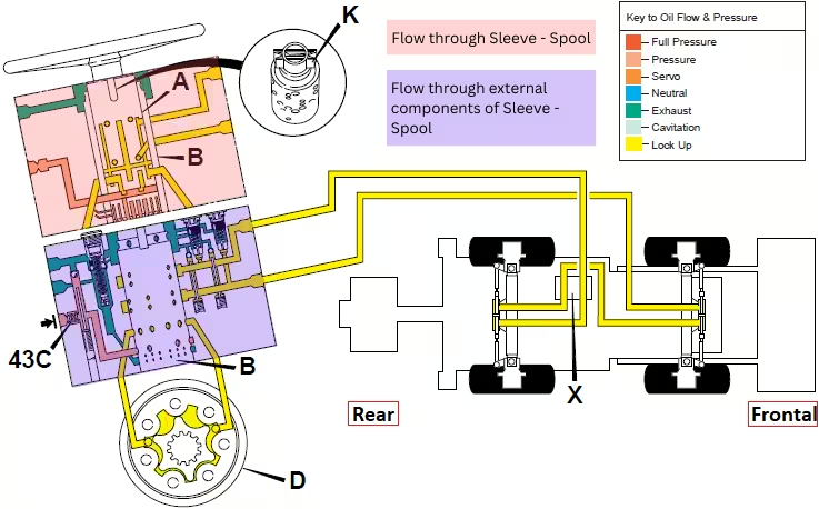
4WS in Neutral Mode
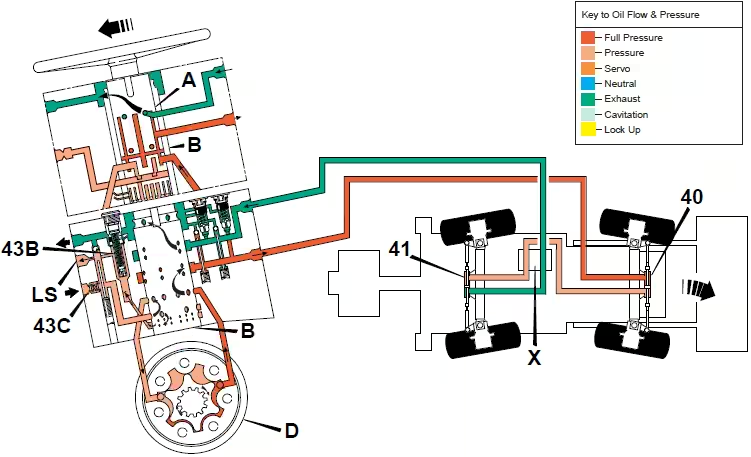
4 Wheel Steer Mode – Left & Right Turn
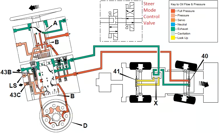
The illustration depicts hydraulic flow through the steering unit during a left-hand turn. When the steering wheel is turned left, the inner spool (A) rotates a few degrees relative to the outer sleeve (B). This movement directs pressurised oil through six of the twelve holes at the bottom of the sleeve (B).
The metering unit is mechanically linked to the spools via a cross pin. As the spool rotates, oil is diverted by the inner spool (A) into the stator (D). The rotor lobes of the metering unit then pump oil to the rear power track rod cylinder (41), causing the rear wheels to turn right. Simultaneously, pressurised oil from the opposite side of the rear power track rod cylinder (41) flows to the front power track rod cylinder (40), turning the front wheels to the left by the required angle.
For a right-hand turn, the operation is identical to that described for a left-hand turn, except that the oil is diverted by spool A to the other side of stator D and cylinders 40 and 41. Refer to the next illustration for a right-hand turn.
4 Wheel Steer Mode – Right Turn (Unassisted)
The illustration shows the steering circuit operation when the engine is stopped. Without hydraulic pump assistance, turning the steering wheel still allows for limited steering control through manual effort.
As the steering wheel is turned, the inner spool (A) rotates until the cross pin engages with the outer sleeve (B).
This rotation meters oil to the stator (D), where the rotor lobes pump oil to the power track rod cylinders (40 & 41) using only manual force.
Since the pump is inactive, oil from one side of the power track rod cylinders is redirected to the opposite side through the non-return valve (F) and if needed, exhaust oil from the system supplements this flow to maintain movement.
For a left-hand unassisted turn, the operation is identical to that described for a right-hand unassisted turn, except that the oil is diverted by spool A to the other side of stator D and cylinders 40 and 41.
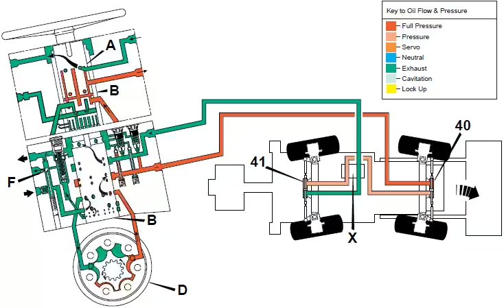
4WS Right Turn Unassisted
4 Wheel Steer Crab Mode – Right Turn
The illustration depicts the hydraulic flow through the steering unit during a right-hand turn in crab steer mode. The operation is similar to the 4-wheel steer mode, with one key difference:
The steer mode control valve (X) redirects pressurized oil from the front power track rod cylinder (40) to the opposite side of the rear power track rod cylinder (41). As a result, the rear wheels turn in the same direction as the front wheels, rather than opposite.
This synchronized movement causes the entire machine to shift diagonally (crab) to the right, rather than pivoting around a turning radius. Crab steering is particularly useful for maneuvering in tight spaces or aligning the machine parallel to a surface without needing to reposition.
Refer below video of machine operating in Crab Steer Mode
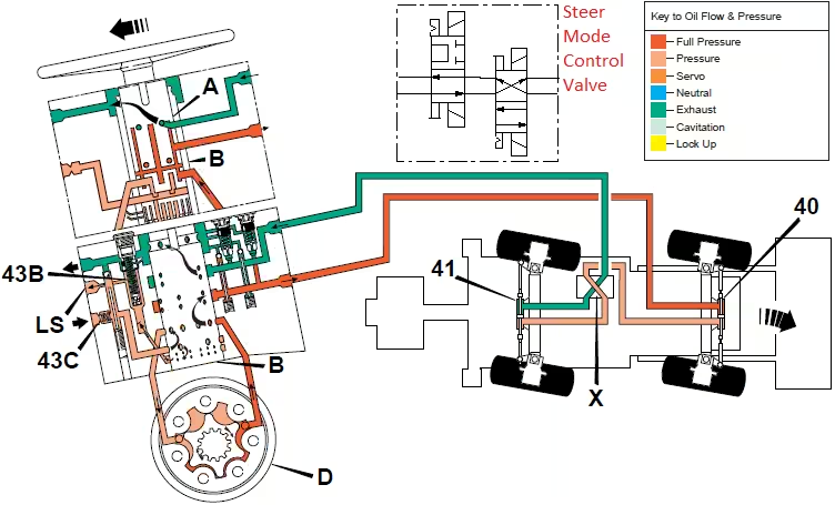
4WS Crab Steer Mode
Crab Steer in a Forklift
2 Wheel Steer Mode – Right Turn
The illustration shows the hydraulic flow through the steering unit during a right-hand turn in 2-wheel steer mode. The operation is similar to the 4-wheel steer mode, with one key difference:
The steer mode control valve (X) isolates the rear power track rod cylinder (41), preventing oil flow to the rear wheels. As a result, the rotor lobes pump oil only to the front power track rod cylinder (40), turning the front wheels to the right. The rear wheels remain locked in the straight-ahead position, held by the trapped oil inside the rear power track rod cylinder (41).
This mode provides conventional front-wheel steering, typically used for higher-speed operations where rear-wheel movement isn’t needed.
2 Wheel Steering – Right Turn
In Previous Post, we discussed Non-Reaction and Reaction circuits and how they function. Both circuits use a spool and sleeve mechanism, and while their designs may differ, the overall working principle remains the same. Insane Hydraulics provided a detailed comparison of the spool and sleeve mechanism in both of these circuits if you’re interested in learning more.
Resources for spool and sleeve mechanism in Non-Reaction and Reaction Circuits:
Non-Reaction Circuit’s Spool-Sleeve Mechanism Part 1
Non-Reaction Circuit’s Spool-Sleeve Mechanism Part 2
Reaction Circuit’s Spool-Sleeve Mechanism
Conclusion
The spool and sleeve mechanism is what keeps a hydraulic steering system working smoothly. It directs oil flow based on how the driver turns the wheel, making sure the right amount of pressure reaches the steering cylinder. Whether the system is in neutral, turning, or switching between different steering modes, this mechanism makes it all happen. Understanding how it works can help in spotting issues like steering lag or uneven response, making maintenance and troubleshooting easier.
(These illustrations are sourced from the OEM Service Manual and are used solely for educational purposes to explain the spool-sleeve mechanism. If you are the copyright owner and have any concerns, please contact me, and I will be happy to remove them.)
What’s Next?
So far in our steering series, we have covered:
Post 1: The applications of steering units, along with a deep dive into their components (spool, sleeve, centering pin, etc.) and design elements (various valves like inlet check, port relief, and load-sensing relief valves).
Post 2: A breakdown of different types of steering units, including open center, power beyond, and closed center steering units. We also explored load sensing circuits and their static/dynamic signal systems.
Post 3: Analyzed steering work circuits, covering reaction vs. non-reaction steering. We also discussed advanced features like 2-speed technology, Q-Amp flow amplification, wide angle steering, and cylinder dampening—along with their applications.
🚀 Coming Up Next (Post 5):
In the next post, we will explore Steering Amplifiers—their working principle, types, advantages, and how they enhance steering performance.
If you enjoyed this post, I’d really appreciate it if you could subscribe. I’m 100% planning to dive deep into hydraulics and break it down into simple terms for you!

