Last updated on December 16th, 2025 at 09:21 am
Hydraulic Tank also commonly known as a reservoir or sump, serves as the storage for hydraulic oil. If properly designed, it will also function as conditioning devices, and if not properly sized, it will break down the entire hydraulic system, as cavitation and contamination problems may occur. This article presents all fundamentals from basics to advanced to properly design and size the reservoir correctly.
Before we dive into the nitty-gritty of hydraulic tanks, let’s tick off the basics of hydraulic tanks.
Function of Hydraulic Tank
The reservoir serves multiple purposes:
A hydraulic tank, or reservoir, performs several critical functions in a hydraulic system:
- Stores Hydraulic Oil: Acts as a reservoir to hold hydraulic fluid.
- Supplies Oil to the System: Provides a steady supply of oil to the hydraulic pump inlet.
- Heat Dissipation: Tank walls function as a heat exchanger, helping to dissipate excess heat generated during operation.
- Prepares Oil for the Next Cycle: Conditions the fluid by allowing time for air and contaminants to separate.
- Entrained Air Separation: Allows entrained air to escape from the hydraulic fluid.
- Contaminant Settling: Provides a space for impurities and debris to settle, improving oil cleanliness.
Types of Hydraulic Tank
Industrial Hydraulic Tank and Mobile Hydraulic Tank
Hydraulic reservoirs in mobile machinery are nothing like those you’d find in industrial plants. In factories, space isn’t much of a concern, so reservoirs can be large and straightforward in design. But mobile machinery has a whole different set of challenges.
(If you like to design Hydraulic Tank for Industrial Application, then refer to this a complete hydraulic power unit design which includes a practical example with a step by step calculation. However general design rule mentioned here applies to Industrial Applications as well.)
With limited space to work with, manufacturers have to get innovative. These reservoirs are often much smaller and shaped in unusual ways to fit snugly into the compact layouts of mobile equipment. Despite their size and shape, they’re designed to perform just as well, keeping the hydraulic system running smoothly even in the tightest spaces.
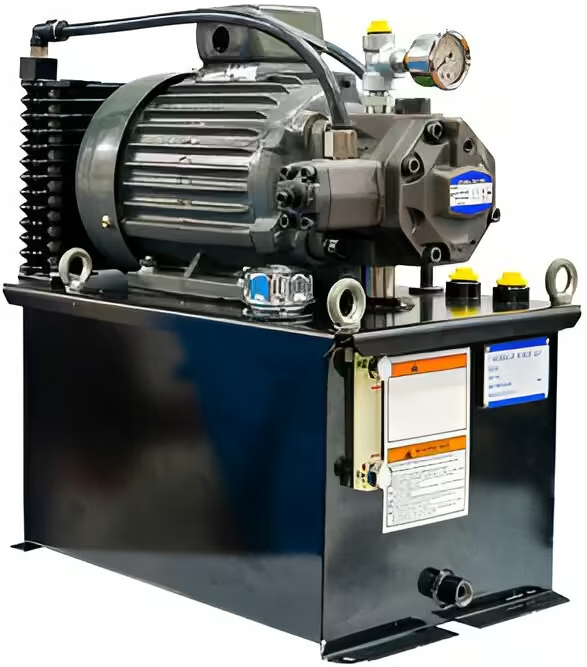
Industrial hydraulic tank equipped with a durable pump and motor assembly, ideal for factory operations.
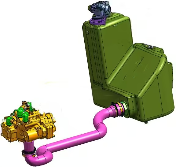
Mobile hydraulic tank featuring a compact and innovative design to fit the restricted layouts of mobile machinery.
Application includes, but not limited to heavy terrain forklift, excavators, backhoe loader, hay bailers as well as military applications.
Some machines, like agricultural tractors, take a different approach by using the transmission or axle housing as their hydraulic reservoir. This design is known as an integral reservoir.
Integral reservoirs typically hold more oil than most mobile reservoirs. However, this design comes with its own set of challenges. The shared space can lead to higher contamination levels, increased heat generation from the gears, and potential aeration caused by the powertrain. Despite these drawbacks, integral reservoirs remain a practical solution in many machines due to their ability to save space and simplify design.
Hydraulic Tank Design Consideration
Hydraulic reservoirs in mobile equipment face unique challenges due to the constant movement of the machinery and the wide range of environmental temperatures they must endure.
Yet, one of the most critical hurdles is the constraint on available space. Size and weight limitations require equipment to operate with tanks that typically require custom design, such that it fits into the exact space available with meeting the technical requirements.
Custom-built hydraulic reservoirs offer a distinct edge over pre-manufactured options, as they can be specifically tailored to match the space and technical demands required for peak efficiency and performance.
Through the use of 3D modelling, users can optimise the reservoir’s structure, ensuring the best possible balance between cost, size, and weight without sacrificing functionality or durability.
For applications where every millimeter of space counts – such as compact wheel loaders – HYDAC’s Cooler Filter Tank combines reservoir, filtration and cooling in a single, space‑saving unit, offering an alternative to a fully custom-built tank while still addressing thermal and cleanliness requirements.
Key Considerations for Hydraulic Tank Design
1. Reservoir Capacity:
– The reservoir should have a capacity of 3 to 12 times the maximum pump output.
– In cases where size and weight are constraints, the reservoir may be as small as the volume the pump discharges in one minute.
2. Shape and Cross-Section:
– Opt for a tall and narrow design rather than a short and wide one to reduce sloshing and minimize cavitation risk.
3. Air Management:
– Design the tank to allow air bubbles to rise naturally to the top of the oil.
– Ensure return pipework is positioned below the oil level to prevent aeration.
4. Breather Cap:
– The tank must be designed to withstand the forces generated by the fluid at the breather cap, whether under pressure or vacuum.
5. Port Separation:
– Maintain a minimum distance of 3 times the suction pipe’s outside diameter between the suction and return ports to improve flow dynamics.
6. Welding Considerations:
– Avoid internal welding where possible to prevent contamination and structural issues.
– Use large welding radii for smoother welding and better structural integrity.
7. Chassis-Integrated Tanks:
– If the tank is integrated into the chassis (e.g., in a telehandler), ensure it remains a closed unit during testing before it becomes part of the structure. This prevents issues with testing and mobility later on.
8. Surrounding Surfaces:
Large flat surfaces in reservoirs can quickly experience high stresses, leading to significant deflections due to the fluid’s weight. When adding peripheral equipment like ladders or air tanks to reservoirs, it’s important to evaluate the plate thickness and the potential need for stiffeners. In Fig.-1, ladders are welded with a hydraulic tank.
In many mobile applications, the fluid level of the reservoir is below the pump inlet.
In addition to pump inlet line losses, this fluid level can create negative pressure, and due to that, the pump may cavitate – i.e., form small liquid-free zones such as bubbles or voids.
When voids collapse and implode near a metal surface, they generate cyclical stress due to the repeated implosions. Over time, this leads to surface fatigue, which results as a form of wear known as cavitation.
To avoid the need for pump de-rating caused by inlet vacuum conditions, the reservoir can be pressurized, helping to sustain the pump’s peak performance.
Hydraulic Tank Pressurising Methods
- Utilise regulated air from the machine’s pneumatic system, if available. This method is generally the most efficient.
- Trap air within the reservoir’s clearance volume (above the fluid) and allow the thermal expansion of the fluid to compress the air, creating pressure within the reservoir.
A pressure cap (breather) helps to maintain the desired pressure inside the tank while also releasing excess pressure. When retracting cylinders, return more oil to the reservoir than the pumps need. The cap should have low-pressure overshoot capabilities. - Source pressurised air from the scavenge pump of a two-cycle diesel engine.
When a reservoir is pressurised, it is essential to calculate the stresses exerted on its walls. (For how wall stress could affect the walls of tank, consider checking out this Video from LunchBox session.)
Hydraulic Tank Components
Sight Gauge
Reservoirs use either a dipstick or a sight glass to check the oil level. Some sight glasses even have a thermometer. Dipsticks are more accurate, but they can expose the hydraulic system to dirt or contamination when removed.
Whether you’re using a sight glass or dipstick, always follow the operator’s manual. It will tell you how to check the oil level properly, including placing the machine on a flat surface, positioning the implements, and checking at the right operating temperature. These steps help ensure an accurate reading.

Sight Gauge in Hydraulic Tank
Baffle Plate Design
A baffle, also known as a dam, is a divider plate placed inside a hydraulic reservoir to enhance its functionality. The primary function of baffles is to prevent return oil from cycling directly back into the pump’s inlet, ensuring proper oil flow and performance.
They also minimize oil sloshing, particularly when the machine operates in uneven conditions. Additionally, baffles contribute to the structural rigidity of the tank walls, which is especially beneficial in pressurized reservoirs. Another advantage of baffles is their ability to trap contaminants, improving the cleanliness of the hydraulic system.
When designing baffles, consider the following:
- Strength: Baffles should reinforce the reservoir structure.
- Oil Flow Distribution: They should ensure uniform oil flow throughout the tank.
- Separation: A clear distinction between suction and return areas is crucial.
- Volume Balancing: Incorporate small slots to balance oil volumes on both sides and avoid dead spots where fluid could accumulate.
- Dwell Time: Extend the oil’s dwell time (the time taken to move from return to suction) to improve cooling and air bubble removal from the oil.
Strategic baffle placement can provide the necessary support for efficient oil flow without adding unnecessary weight or cost. Baffles are also used to direct, contain, and calm the fluid returning to the tank. For enhanced cooling, the return fluid should be directed toward the reservoir’s outer walls.
Baffles can be mounted either at the bottom or the top of the reservoir, positioned perpendicular to the return and suction ports. When mounted at the bottom, the baffle should be submerged 30% below the oil level. For top-mounted baffles, they should be elevated 30% above the reservoir floor. Alternatively, baffles can be positioned parallel to the return and suction ports, guiding the oil in a U-turn within the reservoir.
When sizing baffles, return diffusers, or filters in the return portion of the hydraulic tank, it is crucial to account for the maximum return flow rate, which often exceeds the pump’s output when cylinder with the largest area ratio (difference between the cylinder’s cap end and head end areas) is being retracted at full speed.
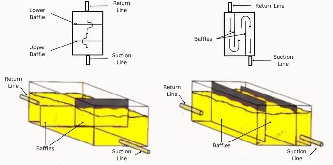
Baffle Plates Placement in Hydraulic Tank: Parallel and Series
Diffuser
In mobile equipment, return line velocities often surpass 10 ft./sec. To reduce this, it’s recommended to size return manifolds or plumbing such that they bring velocities down to 5 ft./sec. or lower. Using return line diffusers effectively slows flow rates and helps mix the fluid without causing agitation.
Diffusers can commonly lower velocities to around 1 ft./sec. or less. Installing perforated metal with 40% open area at the ends of return lines is also effective.

Return Line Diffusers being used in Hydraulic Tank

Desiccant Breathers for Hydraulic Tank
The return flow will surpass the pump’s delivery rate. This happens because fluid returning from the cylinder’s larger side combines with the flow of the retracting smaller side, creating a return flow greater than the flow into the cylinder. Design of baffle should be such that the return flow never aimed at a fluid intake line.
To ensure efficient and safe operation, baffles and other components in the return path should be sized to manage this peak return flow. Return diffusers and filters should be selected with sufficient capacity to prevent excessive backpressure and to ensure proper flow distribution within the tank.
Filler
The reservoir includes an opening at the top for adding oil, often referred to as the filler. Most fillers come with a screen to capture large contaminants during refilling. Removing the screen to speed up refilling is a bad practice because it increases the risk of contamination.
Breather
Breathers in vented reservoirs help filter out atmospheric contaminants and remove moisture from the air entering the system. Some filler caps can double as breathers, but reservoirs can also have separate breather and filler cap assemblies.
Desiccant Breather
A desiccant is a hygroscopic material that absorbs moisture to maintain dryness. You’ve likely seen silica gel packets labelled “do not eat” in packaging bottles or shoes. Silica gel is a common desiccant. Other desiccants exist as well. When moist air enters a reservoir, condensation can form on the interior walls as ambient temperatures decrease. Desiccant breathers, which are multi-layered devices, are commonly used to block moisture and particles from entering equipment such as gearboxes, pumps, and reservoirs.However, the desiccant material has a limited lifespan, so if the breather isn’t replaced at the recommended intervals, it will eventually allow moisture to pass through unchecked.
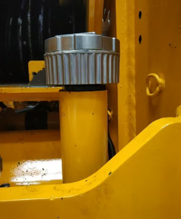
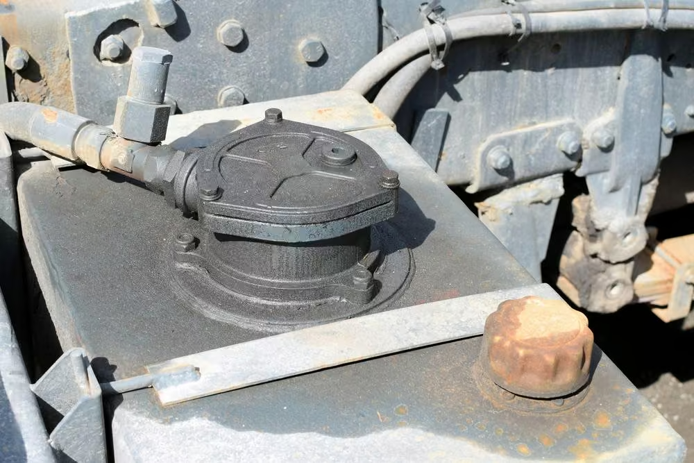
Breather in Hydraulic Tank
Aluminized steel reservoirs offer corrosion protection in the event that moisture enters the system.
This material consists of carbon steel coated with an aluminum-silicon alloy on both sides hot-dipped, effectively preventing contamination issues.
Aluminized steel is also highly compatible with nearly all petroleum-based and synthetic fluids while offering strong resistance to atmospheric corrosion.
Suction Line
The reservoir’s outlet port, also called the suction line, might have an internal suction screen. If the reservoir is too small for an internal screen, an external suction screen assembly can be attached to the outlet port.
The suction line and any internal suction screens should sit about 1/2” to 3/4” above the bottom of the reservoir to prevent debris from being drawn into the system.
For efficient system performance and to avoid issues like cavitation:
- The fluid should flow smoothly from the reservoir to the pump.
- Inlet line velocities should stay below 5 feet per second in larger lines.
- Smaller lines can cause higher pressure drops due to increased fluid shear, so larger lines are better for reducing resistance.
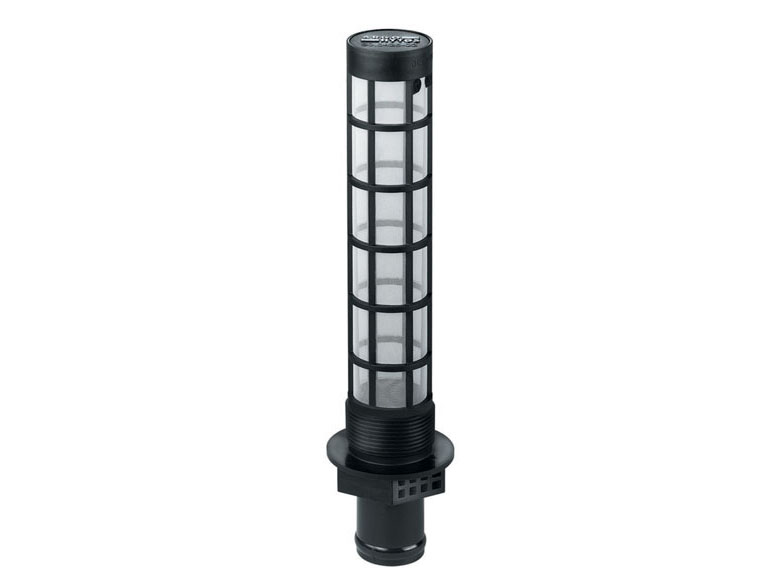
Suction Strainer for Hydraulic Tank from Argo-Hytos
To prevent vortexing (which leads to cavitation):
- Cut the inlet line at an angle and point it downward to increase the throat area and improve fluid flow.
- Position the inlet tube deeper in the oil to boost fluid pressure around the inlet.
- Add vanes to the tube’s throat to stabilise the flow and break up vortex formations.
These simple steps help maintain smooth fluid flow, reduce the risk of cavitation, and extend the pump’s lifespan.
Return Line
Reservoirs receive oil through various return lines:
- Pressurized Return Lines
- Unpressurized Return Lines (Leakage/Case Drain Lines)
Pressurized Return Lines
These lines return low-pressure oil to the reservoir and must be placed below the oil level, ideally 1 inch from the bottom. They also need a baffle to separate the oil from the suction line. Back pressure, usually around 10 psi (0.7 bar), is common. Whenever possible, the ends of return lines should be cut at a 45º angle and directed toward the outer wall. It helps direct the return flow of hydraulic fluid smoothly into the reservoir, reducing turbulence and foam while allowing the fluid to settle properly. By promoting a smoother flow, it prevents the return line from disturbing the oil surface excessively, which could otherwise lead to air mixing in the system. Additionally, this design encourages the fluid to flow across a larger surface area, enhancing cooling efficiency. It also aids in contamination control by ensuring the return flow doesn’t directly interfere with the fluid intake line, thereby maintaining system performance and longevity.
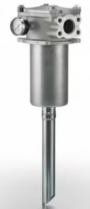
Hydraulic Tank Return Line Filter
Donaldson’s Return Line Filter with 45-degree cut
Unpressurized Return Lines
Also known as leakage or case drain lines, these lines are used in pump, motor, and cylinder circuits. If a case drain line is filtered, it can cause back pressure, leading to shaft seal failure and internal component damage. Thus, filtering case drain lines is not recommended. It’s crucial that the case drain line stays separate from the pressurized return line to maintain zero pressure. The case drain line should be positioned higher than the pump or motor case to guarantee proper oil supply. Improper installation can lead to siphoning, depriving the pump of oil and causing potential failure.
Hydraulic Tank Capacity Calculation
Mobile equipment tanks are carefully designed to fit into specific spaces, which can sometimes make it challenging to achieve the right tank volume. Proper sizing of hydraulic tanks requires thorough calculations and attention to key factors.
When calculating the total reservoir volume for mobile applications, four primary factors should be considered:
- Pump flow for a 30-second period.
- Oil volume below the main pump suction level for emergency steering applications (if applicable).
- Total cylinder extension volume and accumulator oil charge volume.
- Air volume for tank breathing and oil thermal expansion. In non-pressurised systems, the air volume should be at least 10% of the total volume. The air space should also account for the maximum oil volume during operation, ensuring it doesn’t lead to unnecessary breathing cycles.
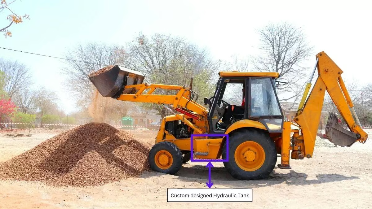
Custom Hydraulic Tank
Drawdown
In a hydraulic system, drawdown refers to the decrease in fluid level in the reservoir as components like actuators, cylinders, and motors consume the fluid.
Ensuring the hydraulic tank has enough fluid during maximum drawdown is crucial. This helps maintain system efficiency, allows contaminants to settle properly, and prevents issues like cavitation or pump failure.
Key Factors in Drawdown Calculation:
- Maximum Output: This involves determining the maximum fluid consumption by the system, typically the volume displaced by the cylinders operating simultaneously.
- Fluid Capacity During Drawdown: The tank must maintain sufficient fluid levels even during maximum drawdown to avoid running dry, which could damage the pump.
- Residence Time: This is the time the fluid stays in the reservoir. A longer residence time allows more air, water, and solid contaminants to settle before the fluid re-enters the system.
Thermal Expansion
Thermal expansion in hydraulic systems is a significant factor to consider because it impacts the total system volume, not just the reservoir. As hydraulic fluid heats up, it expands, and the reservoir must accommodate this change.
Key Factors in Thermal Expansion Calculation:
- Minimum and Maximum Levels: The tank should be designed to handle the fluid expansion without overflowing during operation. Proper level settings help accommodate this expansion.
- Reservoir Management: During heating, expanding oil displaces air through the breather cap’s outlet valve. As the system cools, air is drawn back in through the breather’s inlet valve. This process minimises contamination risks, especially if the breather system is well-maintained.
- Contamination Control: A well-sealed system with effective filtration and breather systems significantly reduces the risk of contamination during thermal expansion and contraction cycles.
By accounting for these factors, you can ensure the hydraulic tank is well-designed to handle all operational demands, minimising risks and improving the system’s overall reliability.
Additional Resources
To properly size the hydraulic tank, it is beneficial to consider below mentioned points.
3D Modelling
3D modelling helps assess how the tank will perform under various conditions, such as gradients. When the machine is at an allowable angle, the oil inside the tank will shift accordingly. Through 3D modelling, you can determine whether the suction strainer remains submerged at both minimum and maximum oil levels, ensuring optimal performance.
CFD Simulation
CFD Simulation for hydraulic tank can be done in static and dynamic condition.
Static Simulation
This simulation helps determine if the minimum and maximum oil levels are accurately calculated based on the breather’s pressure settings. It also evaluates the distribution of return flow into the tank and checks if air is being drawn into the suction line or properly settling out within the tank.

Hydraulic Tank Optimisation Simulation (Source: Parker)
Dynamic Simulation
Addition to the static simulation results, this test replicates real-world conditions, showing how oil behaves during machine acceleration, deceleration, and when the machine is at different angles. Based on these results, the tank design can be optimized, such as adjusting the baffle plate design or relocating the suction port for better performance.
Conclusion
In conclusion, designing and sizing a hydraulic tank is crucial for maintaining the efficiency and longevity of hydraulic systems. A properly designed tank not only stores hydraulic fluid but also helps condition it, preventing issues like cavitation and contamination. This article has covered the essentials of hydraulic tank design, including types, functions, and advanced considerations.
Both industrial and mobile hydraulic tanks have specific requirements, with mobile tanks needing custom designs to fit compact spaces and endure harsh conditions. Key design elements include ensuring adequate tank capacity, managing thermal expansion, and implementing effective pressurization and baffle designs.
Modern tools like 3D modelling and CFD simulations are essential for optimizing tank performance. By focusing on these principles, you can design a hydraulic tank that meets operational needs, maximizes efficiency, and minimizes costs.
If you enjoyed this post, I’d really appreciate it if you could subscribe. I’m 100% planning to dive deep into hydraulics and break it down into simple terms for you!